Facebook
 Google
 GitHub
 Linkedin
Explaining the Tech: Common vs. Isolated PLC I/O Modules
Learn the difference between common and individually isolated PLC I/O modules; how do we know when isolation might be helpful or required for outputs, inputs, and analog signals?
Most PLC racks are filled with modules that look nearly identical from the outside. Some specs, like input versus output, are quite obvious. But certain other things, like common versus isolated channel configuration, may be much more subtle. The differences may be as simple as a single letter within a part number, or a small text indicator along the edge of a module.
So what’s the real difference between common and individually isolated I/O modules, and does it matter?
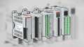
Figure 1. Isolated vs. common: figuring out when to use each is easier than you think. Image used courtesy of the author
For controls engineers and system integrators, the choice between commoned and individually isolated modules isn’t about brand preference. It’s about electrical reference, fault containment, and signal integrity. Understanding what physically changes inside the module makes the decision clearer.
Physical Differences Between Common and Isolated Modules
In a common channel module, multiple I/O terminals share the same electrical reference, usually a shared return (-V) or supply bus (+V). On a digital output card, for example, one common terminal may supply voltage to all outputs at once. Electrically, those channels are tied together on the field side.
In an individually isolated module, each channel has its own isolation barrier between the field wiring and the backplane logic. That barrier is typically implemented with optocouplers or similar isolation components. Each channel operates independently with no shared field reference. This internal difference affects how faults propagate and how signals interact.
Outputs: When Does Isolation Matter?
Let’s have a look at a specific example, with Rockwell’s 1756-OA16 (commoned AC output) versus 1756-OA16I (individually isolated). In the common version, outputs share a field reference. In the isolated version, each output channel is electrically separated from the others.
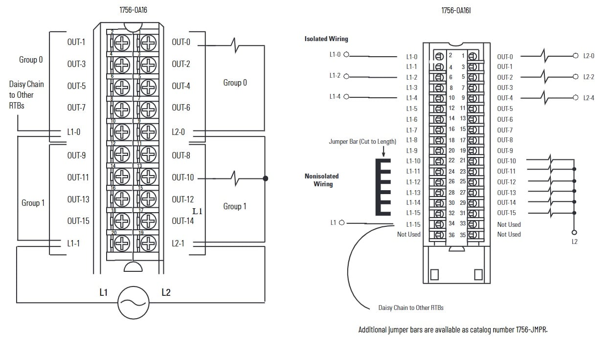
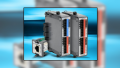
Figure 2. The difference between a common output card (left) and an output card with isolated terminals (right). Images (excerpts from manual) used courtesy of Rockwell Automation
As noted in the manufacturer’s documentation, you can optionally turn the isolated module into a common module with jumpers, but you have the option of using each channel individually.
When are common outputs fine?
- If all loads can safely share the same power supply
- They share the same ground reference
- The field wiring is relatively short
- The environment has low transient noise
When should you consider isolated outputs?
- If the loads are powered from different supplies
- If devices are located in separate panels with different ground potentials
- In the presence of high-energy inductive loads
- Any situation in which a short on one channel must not affect the others
Isolation contains the faults to a single circuit. So a short or transient on one isolated channel is less likely to disturb adjacent channels. However, in panels that may have mixed voltages, containment can prevent trips or module damage.
Digital Inputs: Shared Reference vs. Independence
Input modules generally follow the same logic as outputs; a common input module ties multiple field inputs to a shared return to ground (if sinking) or field voltage (if sourcing). If all sensors are powered from the same 24 VDC supply and share a similar ground reference, then common modules typically perform well. For this reason, common inputs are more often used to conserve wiring effort. For more info on the sourcing/sinking issue, check out this ebook - it’s a pretty complex topic, too much for the scope of this article.
Individually isolated input modules (such as the 1756-IA16I or 1756-IB16I) become important when:
- If sensors must be powered from different supplies
- If field devices are in remote panels
- In the presence of different ground potentials
- In cases where electrical noise is present
Without isolation, ground differences can create unintended current paths or phantom signals. Isolation prevents that by breaking the electrical continuity between channels.
Analog Signals: Where Isolation Becomes Critical
Digital I/O circuits tend to be more forgiving when it comes to small electrical disturbances. A few volts of induced noise or a brief ground interruption will most likely not cause a digital input or output to misbehave to the point of false signalling. Especially when signal thresholds and debounce are well above the noise level and duration. In most cases, a digital signal dramatically crosses, so minor fluctuations are absorbed without noticeable impact.
Analog signals are quite different. A 4-20 mA loop represents process changes across a 16 mA span, and thermocouples generate signals measured in millivolts or microvolts. Small ground differences, induced noise from VFD cables, or common-mode voltage between panels are what make it possible to introduce measurable error rather than simply causing a clean on/off transition, which is especially common in thermocouple installations where long runs pass through high-noise areas, or in 4-20 mA loops powered from remote supplies.
Because analog circuits translate signal magnitude directly into process data, they are far less tolerant of electrical instability, which is why isolation becomes significantly more important in these applications.
4-20 mA Loops
A 4-20 mA loop may be powered by a field supply located hundreds of feet away. If the PLC analog input shares a common reference with other channels, differences in ground potential can introduce common-mode voltage or ground loop currents.
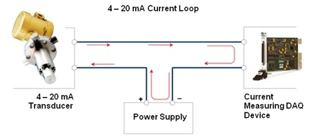
Figure 3. A basic ground loop formation in a 4–20 mA system. Image used courtesy of NI
An isolated analog input breaks the loop at the module boundary, preventing unwanted current flow and preserving signal accuracy.
Thermocouples
Thermocouples generate microvolt-level signals. Even small ground differences or induced noise can introduce measurable error. In thermocouple applications, channel-to-channel isolation prevents noise from one sensor affecting another and protects low-level signals from backplane disturbances.
When Should You Choose Isolation?
Isolation is not automatically better. It adds cost, adds wiring time, and reduces channel density in modules which leads to more modules in the system. When you don’t have the luxury of an oversized electrical enclosure where everything shares the same reference, the added complexity may not provide any measurable benefit. The decision should be driven by system conditions, not by a default preference for isolation.
A practical way to evaluate the need for isolated modules is to ask a few questions during design:
- Are all field devices powered from the same supply and referenced to the same ground?
- Could different panels or machines introduce ground potential differences?
- Are there long cable runs that increase susceptibility to induced noise or transients?
- Do high-energy or inductive loads share the same rack as low-level signal circuits?
- Are you measuring low-level analog signals such as 4–20 mA loops or thermocouples where small errors matter?
- If that is a fault in one channel, can the rest of the system tolerate an electrical disturbance?
What it really comes down to depends on your system. For the most part, if everything uses the same power supply within your system and controlled grounding, common modules will work for your system, but if you are connecting remote devices, utilizing multiple power sources, or measuring microvolt-level signals, using isolated I/O becomes necessary.
Determining whether to use isolated versus commoned modules is less about the I/O card itself and more about understanding how power, grounding, and signal references behave across the entire system.
Featured image used courtesy of Adobe Stock