Facebook
 Google
 GitHub
 Linkedin
Troubleshooting for PLC Modules and I/O Devices
Failures of I/O systems are a common source of headache for control engineers. Troubleshooting those devices that have polarized connections (source vs sink, and NPN vs PNP) is a technique worth refining.

This article follows previous in-depth explanations of two complex topics:
Common Failures and Troubleshooting
When control devices, such as a PLC input or output module, appear to have failed, it is always best to verify proper input voltage first. All I/O modules will have a common terminal listed as C, or perhaps COM, etc.
- If this is a sourcing module, that common terminal should have 24 volts.
- If it is instead a sinking module, the common terminal should have 0 volts.

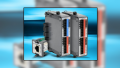
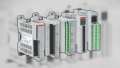
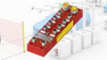
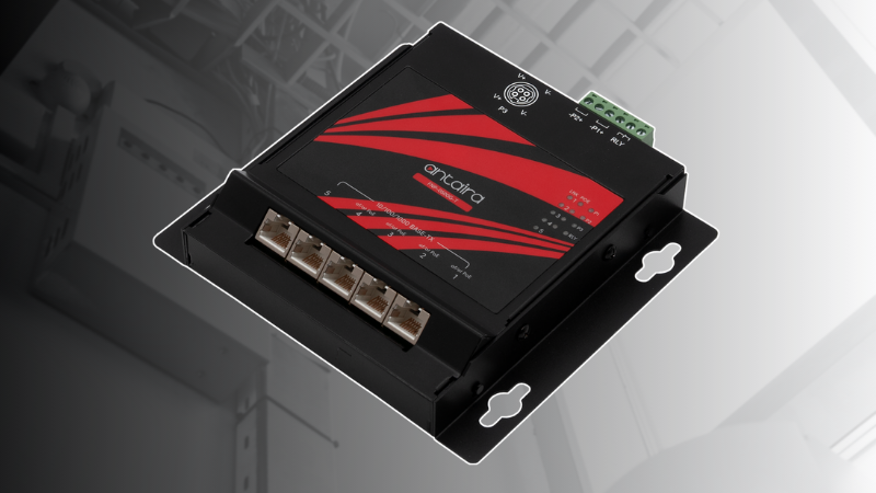
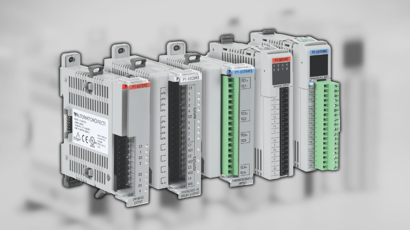
Figure 1. Control and I/O devices require strict attention to troubleshooting detail.
When it comes to testing modern modules and devices, it is impossible to use a continuity test as you might for standard pushbuttons. Resistance inside solid-state components changes when voltage is applied.
Transistor-based devices (DC modules, sensors, etc) require an active, powered circuit. Voltage readings are effective, but this assumes that the rest of the circuit is also working properly.
In addition to voltage, a current meter (ammeter) may be of greater benefit when used properly.
Input Modules
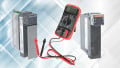
If the module in question is an input module, it can easily be tested by using an inline ammeter - like the ‘mA’ or ‘A’ terminals in a standard digital multimeter.
- Place the red (+) clamp of the ammeter on the input terminal you wish to test.
- Place the black (COM) clamp in the following locations:
- For a sourcing input module, place COM on the - voltage supply. You should see a (positive) value on the order of 5-50 mA depending on the model, Figure 2.
- For a sinking input module, place COM on the + voltage supply. Here you should see a (negative) value, again on the order of 5-50 mA, Figure 3.

Figure 2. Testing of a sourcing input module.

Figure 3. Testing of a sinking input module - be sure to note the negative (-) sign on the meter.
If you see no current, but the module wiring and meter are properly connected, then you most likely have a failed input terminal, or entire module.
Output Modules
For output modules, the process is very similar except that you need a resistor to protect both the module and the meter, it acts as a dummy load device. Find a 1000 Ohm (or 1kOhm) resistor which can be purchased for mere pennies, and attach one end of that resistor to the output terminal. Higher resistance is fine, but keep in mind that the readings below will be lower.
One key difference is this: while an input module is constantly monitoring and allowing current flow, an output module will ONLY supply current if the terminal is energized.
Check the ladder logic or other program source to ensure that the terminal is energized before making this test.
- This time, place the red (+) clamp of the ammeter on the free resistor end.
- Place the black (COM) clamp in the same locations as with the input module:
- For a sourcing output module, place COM on the - voltage supply. You should see a (positive) value around 24 mA, Figure 4.
- For a sinking output module, place COM on the + voltage supply. Here you should see a (negative) value, again around 24 mA, Figure 5.

Figure 4. Testing of a sourcing output module.

Figure 5. Testing of a sinking output module - again, note the negative (-) symbol on the meter.
Once again, a reading of 0 mA current while the module wiring and meter are functioning properly would point to a faulty module that needs replacement, or the module never received the command to ‘turn on’.
I/O Devices
As with control devices, it is always best to check the source voltage of faulty I/O devices first. Most of these NPN and PNP sensors have three wires - meaning three possible locations for the wiring to be the failure culprit. The chance of the I/O device itself actually breaking from normal routine usage is actually fairly rare.
First, check the input voltage across the + and - wires as noted on the wiring diagram. Be sure that the voltage is approximately equal to the required input voltage, also noted on the wiring diagram. A 10-30 vDC and 120 vAC sensor may look absolutely identical except for the small printed voltage range.
If the supply voltage is proper, we can turn to the ammeter again to test these sensors.
Note that the sensor will turn on and off as it is activated. If the sensor is de-energized, the current should be zero. Place an object in front of the sensor, simulating real-world conditions, and the current should begin flowing. Most sensors have helpful indicator LEDs to show the energized state.
Use that 1 kOhm resistor from before and attach one end to the sensor load wire (usually the black wire on a pigtail or quick-disconnect harness).
- Place the red (+) clamp of the ammeter on the resistor’s free end.
- Place the black (COM) clamp in the same locations as with the control modules:
- For a PNP sensor, place COM on the - voltage supply. You should see a (positive) value around 24 mA, Figure 6.
- For an NPN sensor, place COM on the + voltage supply. Here you should see a (negative) value, again around 24 mA.

Figure 6. Testing a PNP Sensor - current goes out through the load wire, through the 1 kOhm resistor, into the ammeter, and finally back to the power supply negative, showing ~24 mA.
I/O Device Signal Noise
Although noise and interference is not exactly the same discussion as the source and sink, or NPN and PNP topic, it can be important when testing sensor operation and function, and so it applies directly to troubleshooting.
Inductive devices such as motors, coils, and solenoids can place unwanted voltage spikes on wires nearby. If the induced voltage is great enough, a momentary flicker of current will be sent through the control device. Often this is too low to be harmful or damaging, but it may be received as an ‘activation’ of the sensor.
One of the easiest ways to guard against this problem is using shielded sensor cables that block the noise voltages. Many sensor cables, such as the popular M12 quick-disconnects can be purchased with a braided or foil shield around the conductors. Beware when ordering generic cables that may not have such shielding and will be more susceptible to faulty signals.
Another simple solution is to route wires a safe distance from devices which may throw out the unwanted inductive noise. Simple in theory, but often physically impossible due to limited available space. Still, if possible, it would be recommended to design a safe distance for the routing of control-carrying wires, as well as to use proper shielded cables.

Summary
Establishing proper device wiring is the first part of an effective design. However, the inevitable repair and troubleshooting as time goes by can dismantle even the best-laid plans. Understanding proper operation and troubleshooting can give longer life to your valuable control systems.