Facebook
 Google
 GitHub
 Linkedin
Sinking vs. Sourcing for Control System Modules - Explained
Digital control systems are particular about the direction of current flow from sensors and input devices. The terms sourcing and sinking (often abbreviated source and sink) are among the more confusing ratings found on I/O module datasheets. Part 1 of a 3-part series.

DC-powered control systems are a familiar industrial staple, but these DC circuits also introduce a few frustrations. One particular concern is the use of the terms ‘sourcing’ and ‘sinking’ with regard to the polarity of the input device and load connections.
These terms are extremely common - nearly every DC sensor, PLC, or robot I/O module will specify such language, or provide wiring diagrams informing the user about how to wire them properly.
A lack of standardization often leads to a long investigation into datasheets and wiring diagrams to ensure equipment safety and proper performance on power-up. Sometimes that single word “source’ or ‘sink’ or even an abbreviation is printed on a module or datasheet, other times, a device may be able to toggle between both modes. In yet other cases, the term is not even listed at all, and you must resort to interpreting a wiring diagram.
DC Circuits
All DC voltage sources, including batteries and power supplies, are marked with + and - terminals. These mean positive and negative respectively, referring to a supply of electrons or a void of electrons ready to receive them. Some argument exists over the actual direction of current flow, but that is entirely irrelevant to our current topic.
In common terms, the + positive terminal is considered the ‘source’ of the electricity, and the - negative terminal is the return back to the lowest voltage potential. This is often called ‘ground’, ‘DC neutral’, or simply ‘negative’.
Since DC, by definition, always forces electron flow in one consistent direction, it is critical that any transistor-based devices, since they are composed of diode junctions, must be connected with the terminals in the correct order.
Any device that completes the path from + to - should, in theory, allow electricity to flow in a properly functioning circuit.
AC voltage systems are not concerned with issues of polarity. AC sensors and loads are not usually restricted as to which wire supplies the live L1 or neutral N wire, since it will exchange polarity many times per second.
We must face the question of sourcing / sinking in either of these two scenarios:
- If a DC input or output terminal is used in any control equipment. PLCs, VFDs, remote I/O modules, etc.
- If an input device is constructed with transistors, which includes nearly every 3-wire prox, photoeye, and ultrasonic sensor on the market.
Definition of Source vs. Sink
The words themselves are simple to define, therefore we begin with these statements so that all following examples will be more easily understood.
Sourcing: Providing the (+) voltage supply.
Sinking: Providing the (-) voltage return path.
Input Terminals
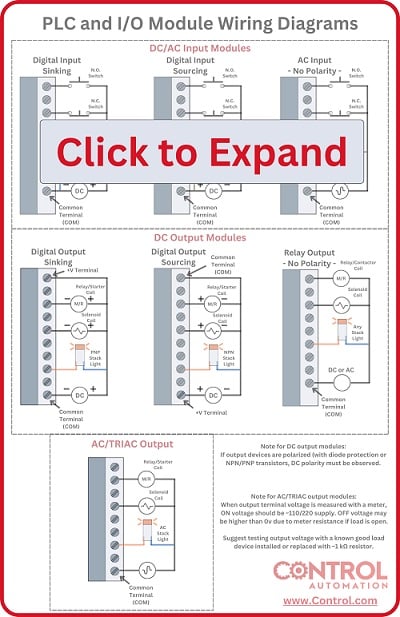
Any controller using DC inputs will be subject to this discussion. The most common style of input terminal is ‘sinking’, since it follows a more typical layout that our logical minds tend to follow. But be aware that input modules may be either sinking, sourcing, or selectable between both, as the three images below illustrate.

Figure 1. Sinking input I/O module. Image used courtesy of Rockwell Automation

Figure 2. Sourcing input PLC module. Image used courtesy of Rockwell Automation

Figure 3. Selectable input PLC module. Image used courtesy of Automation Direct
The common ‘sinking’ input terminal means that the path back to the (-) supply goes through the terminal, and usually out through a common terminal nearby. If you want to supply a proper signal, you must provide a +24 volt level at the terminal in order to complete the circuit. In a simple line diagram, it would appear as shown below.

Figure 4. Sinking input circuit diagram
This means that any device attempting to send a signal to the sinking input terminal must be 0 V when de-energized, and 24 V when energized.
The other (less common) option is the ‘sourcing’ input terminal. This means that the terminal is always powered with 24 volts, so it’s the source of electricity for the input device. Rather than current flowing IN to the input terminal, it flows OUT of the input terminal. This is opposite from the way most people logically imagine an input circuit, so it tends to be more confusing. But it is important to remember the facts about creating a circuit. As long as a path is established between + and -, current will flow. This doesn’t change just because the module is an input versus an output function.
The following diagram shows how this sourcing input operation would appear in a circuit.

Figure 5. Sourcing input circuit diagram
In both cases, all input terminals contain a resistor (they call this ‘input impedance’), so there is very little risk of damage to an input terminal just by connecting the incorrect polarity. Providing the wrong voltage however, will likely destroy the terminal.
Output Modules
Most of the same rules apply to outputs just as they do to inputs. The only difference is that most wiring scenarios are simpler since nearly all output devices can be used with either kind of output terminal. One exception may be an LED stack light with a common terminal. These devices will be either sourcing or sinking, but even in this case they can usually accept both polarities.
This does not mean that you should disregard polarity when wiring the output devices. Many coils are protected with diodes which, if wired in reverse polarity, allow a virtually unlimited flow of current. Output terminals are not outfitted with a current limiting resistor like inputs are, and they can be damaged if too much current is allowed. This is a caution, but overcurrent is outside of the scope of this article.
Most output terminals are sourcing, which means these terminals supply 24 volts when energized. The resulting current travels through the load device back to the DC negative supply. If the load device is marked with + and - (like a relay with a built-in diode), then the + should connect to the output terminal, and the - should return to the power supply negative. The diagram below shows a functioning sourcing output.

Figure 6. Sourcing output circuit diagram
In the less common case of a sinking output, the terminal supplies the direct path back to the negative voltage supply. Therefore, when energized, the voltage should be 0 volts. However, when de-energized, a voltmeter will not show 24 volts unless the load device is connected and functioning properly. So in the case of sinking outputs, they cannot be tested with the load disconnected. The diagram below is an output circuit with a sinking output configuration.

Figure 7. Sinking output circuit diagram
What Does Sourcing and Sinking Mean?
This article explored the definition of sourcing and sinking for control system input and output modules. Further articles explore the related concepts of PNP and NPN for the field devices that connect to these modules.
Related Content