 Facebook
 Google
 GitHub
 Linkedin
Understanding NPN vs. PNP for 3-Wire Sensors
You are bound to encounter two terms associated with sensors and some loads: ‘NPN’ and ‘PNP’. You must understand the relationship between the field device and the control module in order to choose and install components properly when needed.

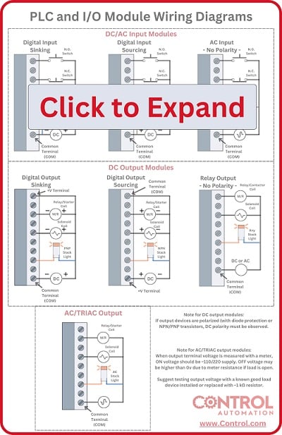
Every control system needs some sort of connection to the environment and conditions in the physical process around it. These devices are most commonly called ‘I/O’ devices for inputs and outputs. Identifying the correct wiring of a device is crucial for the success of the system in both initial wiring as well as maintenance and replacement.
The Difference Between PNP and NPN Sensors
Two terms are associated with sensors (and even some loads): ‘PNP’ and ‘NPN’. The concept is closely related to I/O modules which can be listed as Sourcing or Sinking, and you must understand the relationship between the two in order to replace components properly when needed.
For DC 3-wire sensors, two types exist. This makes sense considering the two types of input modules with which those sensors will interface.
We will start with a summary, and then define the reason and the background for such a summary:
PNP (often called sourcing) sensors provide a positive output, to be used with sinking input modules.
NPN (or sinking) sensors provide a negative (0 v) output, to be used with sourcing input modules.
PNP vs NPN 3-Wire Sensors
The only devices that are limited in compatibility are those with diode or transistor construction, as noted previously. That means that mechanical N.O. and N.C. buttons and switches can be used with either style of input. Indicator lamps and most coil load devices can be used with either style of output. This is good news because you do not ever need to examine a pushbutton to learn its NPN or PNP polarity - it has none.
These buttons can be installed upstream between power and the PLC (power side switching - more common), or they can be installed downstream between the PLC and ground (ground side switching - less common).
PNP and NPN refer to the transistor types providing the output voltage. The main difference between these two transistors is the direction of current. In the PNP sensor configuration, the wire providing the output signal will supply a positive outgoing current when energized. This is exactly what the sinking input modules require to function properly.
Side note: the science of the diode junction construction that gives NPN and PNP their respective names is not the objective of this article. Here we only wish to address their application in control systems.
Sensor polarities are not always labeled directly on the device, but wiring diagrams are usually found on the body somewhere. A PNP sensor is recognized by the label attached to the signal wire (usually the black wire). It will indicate a + voltage, either by giving a direct + notation, or by showing a rectangular ‘load’ that also connects to the - line. If the sensor provides the + signal, then the input module must provide the opposite negative connection.
The diagrams below show a couple of actual examples of a PNP sensor wiring diagram. Notice in both cases, the black wire is connected to a rectangular 'load', the other side of which connects to the - signal line.

Figure 1. PNP sensor wiring diagram as found in a datasheet.
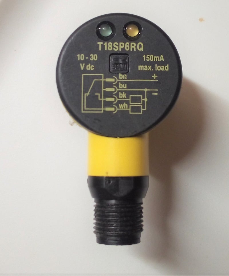
Figure 2. The PNP sensor wiring diagram is directly printed on the back of this sensor. Image used courtesy of Control Automation
The NPN sensor will provide a direct path to receive current from the output signal wire directly to the negative power supply terminal when energized.
The wiring label for the NPN scheme shows a load device (the same rectangle as before) connected to both the sensor signal wire, as well as to the + supply line. This should illustrate the constant positive supply from the input module, allowing the sensor to provide the path to the negative supply.
The diagram below shows an NPN wiring schematic. Notice how it is very similar to the previous example, but the rectangular load is connected to the black signal wire and the + supply line.

Figure 3. NPN sensor wiring diagram as found in a datasheet.
What Happens if You Reverse the Wiring?
Remember before, we said that PNP must be used with sinking modules, and NPN must be used with sourcing modules? What happens if you connect the wrong combination?
One tricky concept regarding sensors is that it would seem that these two sensors are simply the opposite of each other. The voltage seems to swap between high and low for both sensors. This is not the case.
Because they are built with transistors, which use diodes, current will only flow when energized, and it will only flow in one direction for each sensor. This means that you cannot connect a PNP sensor to a sourcing input and expect a simple reversal of on/off states. It will simply not work at all.
To explain this fact, when a PNP sensor is energized, it provides a positive 24 volt signal to the input module on the controller. But, if the module is providing the same positive voltage back against the sensor, no current will flow at all when the sensor is energized.
Then, when the sensor is de-energized, the transistor blocks the flow of current in either direction, so no current will flow at all.
As you can see from both of these cases, this sensor would simply never energize the input. But the good news is that it will not damage the input, so if you make this mistake, it may cause the machine to not operate correctly, but you didn’t cause extra damage to the module or the sensor.
Load Devices: NPN vs PNP Transistor Output
Nearly all load devices can actually be used with either sourcing or sinking outputs, since both modules allow the completion of a circuit from + to -. It is rare to encounter output devices that are restricted to either PNP or NPN, but it can be seen on some light towers and other devices, so it’s still important to understand the relationship.
Consider a large solenoid valve or relay with diode protection. The input connections on the valve will be clearly identified with their own + and - polarity to allow proper use of the diode.
If used with a typical ‘sourcing’ output, the power supply + will be connected directly to the common terminal of the output module. The output terminal will then supply that positive voltage to the positive side of the coil. The negative side of the coil returns the current directly to the power supply -. This means that the load has been connected in ‘sinking’ configuration. If the load device was transistor-based, this would be an NPN load.

Figure 4. Sourcing output module, whose common terminal is directly connected to the power supply, with a sinking load (in the case of an NPN load device). Image used courtesy of Control Automation
Now consider the same coil paired with a ‘sinking’ output module. In this case, the output module is connected with the common terminal directly to the power supply -. Therefore, the positive voltage must be provided by the valve. The + side of the valve connects directly to the power supply +, and the - of the valve goes to the output terminal. Since the load is providing the positive voltage, it is wired in ‘sourcing’ configuration. Compared to the previous example, this load device would be PNP if it were transistor-based.

Figure 5. Sinking output module, which is directly connected with the common terminal to the power supply, with a sourcing load (in the case of a PNP load device). Image used courtesy of Control Automation
Sensors, Polarity, and Basic Circuit Theory
If you work with sensors and field devices in a control system, you are guaranteed to encounter this concept of PNP and NPN, but with some practice and familiarity, it always turns back into the simple foundational concept of electricity: the practical flow of current to complete a circuit.


Remembering Field Sensing Devices
NPN = More “N’s”, Negative Switching (INput module should be PNP)
PNP = More “P’s”, Positive Swithching (INput module should be NPN)