 Facebook
 Google
 GitHub
 Linkedin
A Look Inside the Circuit Construction of an NPN and PNP Sensor
Most engineers are familiar with the basic control system terms of sinking and sourcing, or the NPN and PNP terms from which they are derived. But how exactly do those transistors play a role in inputs or outputs?

Background: What are Sinking and Sourcing?
When dealing with discrete inputs or outputs, we must understand if the device is sinking or sourcing. These terms refer to which device provides the power and which provides the ground since both must always be present.
A sinking input provides the ground, whereas a sourcing input provides the power. Incorrectly wiring a sinking device could damage the device because you would be applying current in a reverse direction. In many typical control systems, the output modules are sourcing, and the input modules are sinking. So if we connected a sourcing output module to a sinking input device, the system would correctly detect the state of the output.
Before we investigate the transistor terms of NPN and PNP, the figure directly below shows a sinking PLC input, we can see that voltage will be switched on or off by the switch, which the PLC will recognize as the input ON or OFF.
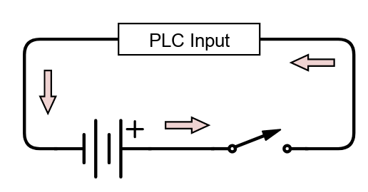
Figure 1. The simplified version of a sinking PLC input using an electromechanical switch to supply current (no transistor yet). Image used courtesy of Control Automation
The next figure shows a sourcing PLC input, and we can see that the ground or common connection is going through the switch instead of the power.
It is important to note that the same switch can be connected in either scenario. The switch itself is not limited to being either sourcing or sinking.

Figure 2. The simplified version of a sourcing PLC input using an electromechanical switch to supply the common return path (no transistor yet). Image used courtesy of Control Automation
NPN and PNP Transistors in Sensors
3-wire sensors also have defined sinking and sourcing types, but they are commonly referred to as NPN or PNP. Negative-Positive-Negative (NPN) is equivalent to sinking, and Positive-Negative-Positive (PNP) is the analog to sourcing.
These terms are commonly used with sensors or relays, defining how the device needs to be wired. When activated, an NPN sensor will enable a path to ground (DC common return). If we look at a transistor with a base (B), emitter (E), and collector (C), current will flow from the collector to the emitter when enough positive current is present at the base.
This example shows how an NPN optical photoelectric sensor may provide the required current when a certain wavelength of light (usually of adjustable intensity) is presented to the sensor. The PLC supplies the signal wire current, and a small amount of current will flow to the blue wire when the sensor is energized. The module will recognize this as an 'energized' or 'true' signal.

Figure 3. Circuit diagram of an NPN sinking sensor showing the well-recognized 3-wire sensor connection colors and the sourcing PLC module. Image used courtesy of Control Automation
A PNP sensor works oppositely—when the sensor is activated, the signal terminal will have voltage; when the sensor is not active, the signal will be zero volts. The same is true with transistors. With a PNP transistor, current will flow from the emitter to the collector and the base when the base is provided with a path of sufficient current.
Because the sensor's function changes depending on whether the sensor is PNP vs. NPN, it is very important to know what type of sensor you are using. Since the internal construction of a transistor is two opposing diodes, current from the PLC cannot flow if the wrong kind of sensor is used. Therefore, if the wrong sensor type is used, the signal will always appear as 'false' or 'low'.

Figure 4. Circuit diagram of a PNP sourcing sensor showing the well-recognized 3-wire sensor connection colors. Image used courtesy of Control Automation
Why Is There an NPN Sensor and a PNP Sensor?
This may all seem confusing, and you may be wondering why we even have different types of sensors and transistors. There are a few reasons, and one is location. In my experience, PNP sensors are commonly used in North America, but this is not a hard rule.
No electrical safety standard dictates using PNP sensors in North America; however, consider the entire I/O system. A PNP sourcing sensor is matched with a sinking controller input module. Each input terminal is internally grounded through the module. If a wire were to contact a metal machine chassis, the result would be an inactive terminal. Conversely, an NPN sensor would require a sourcing module with a live 24 V at every input terminal. If any wire were to come loose now, a ground fault would occur.
On the other hand, NPN transistors can transmit signals faster than equivalent PNP devices since the electronic mobility of N (negatively) changed particles is much faster than P (positively) charged holes in the silicon device. So for high-speed switching applications like high-speed encoder signals or PWM (pulse width modulation) control, you might want to look at NPN-style I/O modules.
The NPN transistor is preferred as a current amplifier in many devices since it reacts to positive voltages at the base input. This means that typical controllers, like the small Arduino and similar platforms, can easily drive an NPN transistor. However, the advantages of sourcing sensor construction mean that PNP is the go-to choice for many sensor applications.
A Note on NPN and PNP Output Safety
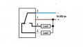
When considering an output module, safety systems, or motion devices that could cause harm, we should use PNP outputs or sourcing-style relay connections because of the possibility of unexpected motion. This is closely related to the concept of power-side and ground-side switching.
With an NPN device, the scenario of the signal connection finding a ground would activate the device. This means if the cable wears away and exposes the signal wire, and that wire happens to ground itself out, you could have unexpected motion as the device controlling the motion would be bypassed. This could happen while people are inside guarding and working on equipment. Some might argue that switching negative reduces arch flash and is less wear on the contacts. While this may be true for larger current circuits, control circuits typically use low voltage, ~24 VDC, and low current.

Figure 5. Comparison of NPN and PNP outputs and what might happen if a fault (red dashed line) were to occur. Image used courtesy of Omron Automation
In the safer version using a PNP (sourcing) module to control a sinking load, the case of a grounded signal wire would bypass the load, not the control. There may be some overcurrent damage to the control module, but the motion device will not be activated, and a higher degree of safety is achieved.
Featured image used courtesy of Adobe Stock
Related Content


“and you may be wondering why we even have different types of sensors and transistors.”
Price was one of the main reasons. 30+ years ago NPN transistors where more common and less expensive. NPN is grandfathered in.
It is a PIA trying to explain it to some of the panel builders and still catches me out occasionally. As humans I think we are hardwired to understand PnP. It makes a lot more sense to a tech to ground a meter on a 0V terminal and check to see if 24V is present than the other way around,