Facebook
 Google
 GitHub
 Linkedin
A Guide to Identifying and Using PNP Sensors
Why do we need to use PNP sensors in certain applications, and which markings and diagrams allow us to identify these devices?

Integrating sensors into control systems can be a tricky process. Not only is there a wide diversity of sensor types, but there are also competing electrical characteristics
I love programmable control systems. They are efficient and use less electricity than an equivalent analog wired control, and that wiring is going to be far easier for a digital control system.
Programmable systems are also easier to optimize, change, and improve in mere seconds without any new hardware required. I can access the data from nearly anywhere in the world and monitor vast operations with just a couple of network cables.
But let’s face it, some of the terminology and device requirements for digital systems can be very confusing. This confusion is plain to see when discussing sensors and their wide array of sensor types, polarities, and normal states.

The back of a typical PNP optical sensor. This sensor shows the connection to the load device with both Normally Open and Normally Closed options.
In this article, we will clarify the purpose and application of PNP sensors, how to confidently identify the polarity of a PNP sensor, and the basic reason behind the name, which sounds non-coincidentally just like a bipolar transistor.
How Does a PNP Sensor Work?
The distinguishing factor of a PNP sensor aside from any other sensor or input device is that, when the internal contact is connected, the current is sent out from the sensor, and into the receiving controller.
The reason that programmable control systems, in particular, are sensitive to properties like polarity is that digital electronic devices contain ‘diodes’ which allow the flow of electricity in only a single direction.
In contrast, many analog devices such as incandescent light bulbs can accept electricity in either direction - or even both directions with an AC input. This is commonly seen on lights, relays, solenoids, and many other devices. But digital electrical systems absolutely must be connected properly.
There are two directions that electricity might flow, and to remain consistent with manufacturers’ prints and diagrams, all flow directions will be conventional from +v to -v. The two directions we might consider are current IN TO the digital circuit, or current OUT OF the digital circuit.
The input module of a PLC, VFD, or any other control device is designed to sense when a circuit on any of its terminals allows current to flow. This indicates that the contact is closed, and it becomes ‘true’. The input terminal itself is a part of the circuit - it has to be, otherwise current could not flow.
If we have a type of digital input that expects current to flow into its terminals, then we must have a type of sensor that sends current out. As stated before, this is exactly the function of a PNP sensor.

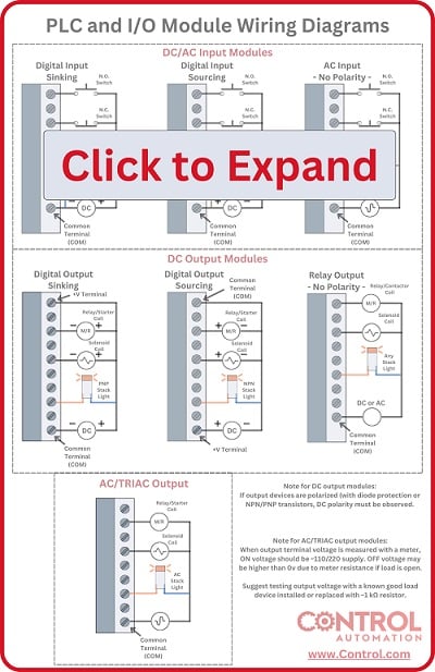
The wiring diagram of a proximity sensor showing the direction of the current flow out of the sensor, indicating the PNP polarity.
If a device sends current out, we call it ‘sourcing’. Therefore a PNP sensor is also called a ‘sourcing’ sensor.
This is easy to remember because the sensor is the source of the current. If a device accepts current in, then we call it ‘sinking’. That means the sourcing sensor must be used along with a sinking input module. The term sinking can be remembered because a sink has a drain leading down to the lowest potential area, ground.
Identifying a PNP Sensor
It is very important to be able to distinguish when you have a PNP sensor, or when your digital controller requires a PNP sensor input.
In order to identify the sensor, we can use the datasheet, or often the diagram on the side, and even a voltmeter.
The datasheets will always list the polarity of a device that is PNP (or its partner, NPN). Using a search engine, type in the part number and ‘datasheet’ and the information will be provided. The term sourcing may also be used to identify a PNP polarity. In many manufacturer’s part numbering schemes, a P will give away the polarity.
If a datasheet is not readily available, but a diagram is printed on the side or end of the sensor, this diagram will have some way of identifying a ‘load’ device. Sometimes the word LOAD may be seen.
Sometimes, a small rectangle with lines on both sides will represent the load. Other times, an arrow on one wire may indicate which direction electricity flows to or from the load. But no matter the case, the PLC terminal is our ‘load’.
If an arrow points toward the load, this means current is sent OUT from the sensor, so it’s a PNP type. A load rectangle will have two lines connecting to it, one from the sensor, and the other connecting to either + or - voltage.
If the load rectangle connects to the - voltage, this means that the load returns to the ground or is a ‘sinking’ type load. So the current must be sent IN TO the load, and OUT from the sensor, and we have positively identified a PNP sensor.

An example wiring diagram of a standard PNP style sensor. The load rectangle symbol connects the sensor to - voltage, indicating the PNP polarity.
A final check uses a voltmeter, as long as the sensor is working and connected properly, otherwise, the tests may not prove anything.
First, disconnect the load wire going off to the PLC. With the COM lead of the meter connected to -v ground, measure the voltage at the load wire. When the sensor is activated and deactivated, the voltage should swing between 0v and 24v.
Measuring 24 volts indicates that the sensor is applying power, and attempting to send current out to the PLC. This is a PNP sensor.
At the same time, you may test to verify whether the PLC requires a PNP sensor connection. With that load wire still disconnected, and the COM lead still in the -v ground, measure the PLC input terminal.
If you measure 0v, it means that the module will readily accept current in, ready to send it to ground. This is exactly the module that a PNP sensor was meant for.
Why is it Called a PNP Sensor?
The name PNP goes along with the similarly named PNP bipolar junction transistor. In a PNP transistor, current is sent into the emitter pin, and out through the base and collector. When current flows through the base pin, a much larger current is allowed to flow through the collector.
In a PNP sensor, the load device is connected to the collector pin. When the sensor activates by whatever sensing element it uses, this allows current through the base, and sends a larger amount of current out through the collector, off to the load.

A typical 2-wire diagram illustrating how to connect the load device to either -V to act as a PNP sensor, or connected to -V to act as a PNP sensor.
Sending current out of the sensor is the very definition of the PNP polarity type. The naming convention of the sensor is no accident, it was very intentionally constructed with a bipolar transistor construction and bears the name.
PNP (sourcing) sensors are unique in their polarity of only allowing current to be sent out to a load device and must be matched with the correct load to accept current in (sinking). They can be identified directly with a datasheet, or with a diagram in which the load device directly connects to -v ground.
Finally, they can be verified by measuring 24 volts on the load wire after the wire has been disconnected from the load.
Diagrams courtesy of data sheets on AutomationDirect.com.