Facebook
 Google
 GitHub
 Linkedin
How to Measure Resistance with a Multimeter
When the power is removed to a circuit, the common measurements of voltage and current prove meaningless. The only remaining option is to use resistance testing to determine which components and conductors are working.

In most situations, a measurement of voltage or current is most useful to track down a failure in a control circuit. Voltage requires only that power is applied; the load does not need to be active. Current measurement does require the circuit to have electricity actively flowing, but clamp-type meters allow this to be a simple measurement.
However, if the power must be removed from the circuit, then neither of these two measurements can properly show any information and an alternative must be used. The most common of these alternative measurements is resistance.
What is Resistance?
In descriptive terms, the resistance value allows us to determine how much current would pass through a device if the proper voltage were applied.
Mathematically, the resistance is the ratio (division) between voltage and current:
$$R=\frac{V}{I}$$
The relationship between resistance and current is inverse, so high resistance leads to low current, and low resistance leads to high current. The base unit for resistance is Ohms (Ω). Due to the inverse nature between resistance and current, we could infer that for circuits with several amps of current, the resistance will be reported in its basic Ω unit. For smaller circuits, with current in milli or microamps, the resistance will be measured in kilo or megaohms (kΩ or MΩ).
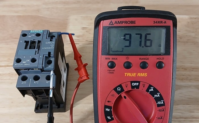
Figure 1. A resistance test of a contactor shows a coil resistance of around 97 Ohms. According to the part datasheet, the value should be 98 Ohms; so this one works well.
A resistance value of nearly zero is considered a short circuit. This low resistance leads to a virtually unlimited increase in current, which should cause a fuse or breaker to trip with excessive current. At the other extreme, a very high resistance value is displayed on a meter with the text OL (over limit), indicating an open circuit. When the resistance is nearly infinite, the current will likewise drop to basically zero.
Benefits of Resistance Measurements
When used properly, the resistance value can actually teach us more than voltage or current alone. In a control circuit, voltage always tends to be lost either at the load device or at the first point at which the circuit is ‘open’. This may be an open switch or a broken wire, among other reasons. But no matter the reason, the voltage drop will simply equal the full source voltage - it does not give us any indication of how much electricity is flowing. An open switch which measures 24 volts will lead to zero current flow, but a load device which measures 24 volts will lead to some non-zero current flow, even though the voltage measurement is the same.
So we can see that resistance allows a technician to verify two separate facts about the circuit.
- First, if some measurable amount of resistance exists in the circuit (not zero, but not OL), then we can say with certainty that some current will be flowing when the circuit is properly connected and powered.
- The second fact learned from resistance is how much current will be flowing when power is applied. This is a fact that voltage measurements cannot determine, so in some cases, resistance may be more important than voltage alone. If a relay coil has partially failed, it may still drop all of the source voltage just like before, but the current draw may be different. Resistance could prove that the relay will conduct some current, and it may show exactly how much current will flow.
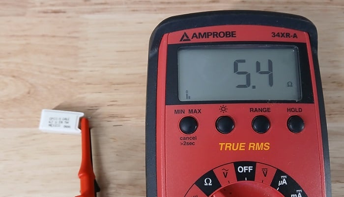
Figure 2. A resistance test for a power resistor. Although difficult to see, the printed value is 4.7Ω. The meter leads are adding about 0.7 extra ohms.
Earlier, we stated that power must be removed to perform resistance tests. It’s important to understand the function of the meter in order to make proper tests that show the correct information.
Caution Against Added Resistance
Remember that any extra cable length (even the meter's own leads) will add some slight resistance. A wire may have less than 1Ω of resistance, but that might be significant for some resistors. If the nominal value is in the thousands, a few extra tenths of an ohm wouldn't even be worth mentioning. However, if the resistor is only a few ohms to begin with, like in Figure 2. above, one extra ohm would be a massive change!
Cautions Against External Voltage
When testing resistance, the meter develops its own voltage to send electricity through the test device. This voltage comes from the battery. The test device drops some voltage, and the meter internally drops the remainder with a series voltage divider. Using the ratio of internal fixed-resistance and measured vs. battery voltage, the test device resistance can easily be calculated and displayed.
However, if the leads are placed on a live circuit, the internal measured resistance may be more than the battery source voltage. This seemingly impossible scenario is shown on the display as a negative resistance. If you see a negative value shown on the screen, remove the leads immediately. It probably didn't do any lasting damage to the meter, but a high voltage certainly can be damaging. If the meter is manually-ranging, the lowest resistance scales will be the most likely to be damaged by an external voltage.
To give absolute peace of mind, simply remove one of the wires leading to the device. This will ensure that the device cannot be a part of the active circuit.
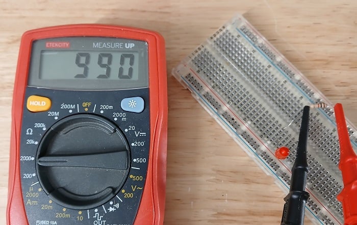
Figure 3. To guarantee proper readings, try to remove at least one connection of the resistor, isolating the component from the rest of the circuit.
AC Devices
Since the meter only provides DC voltage for its test, we will be forced to ignore any effects from the circuit that only happen when AC power is applied. Capacitors and inductors both behave very differently under the influence of AC power. Therefore, we might try to measure these components with a standard multimeter, but we will not be measuring the real effect of the circuit.
Always consider that, when AC voltage is applied in the working circuit, the DC resistance has some effect, but the AC reactance also has some effect, leading to an overall AC resistance known as impedance, and it will always be a bit larger than the DC resistance alone.
Learn more about AC power here. It's too complex to cover in the scope of this article.
Solid State Devices
The other caution that deserves emphasis with all modern electronics is when we attempt to test solid-state devices. In purely resistive circuits, the phrase ‘linear’ means a constant resistance for all voltages: raise the voltage and the current will also increase at the same rate. However, for solid-state devices like diodes and transistors, the amount of applied voltage may change the resistance.
Common sense can be very misleading here because the device under test may show a legitimate resistance value when removed from the circuit, leading the technician to believe the device is working properly. However, when returned to the circuit and the circuit voltage is different, this may drastically alter the resistance. In these cases, it’s important to use voltage tests when the circuit is live for solid-state testing. Often, a small value resistor is placed in series with a solid-state device. Measure the voltage of the resistor, and along with its voltage, current can also be calculated.
Like using multimeters? We do too.
So much so that we published a downloadable eBook: The Guide to Digital Multimeters
Here are the other great multimeter articles:
- The Importance of Multimeters
- Understanding the Different Types of Multimeters
- How to Choose the Right Multimeter
- How To Measure DC Voltage With a Multimeter
- How to Measure AC Voltage With a Multimeter
- How to Use a Multimeter to Measure Current
- How to Measure AC Current Using a Clamp Meter
Revised - original article published June 2020