Facebook
 Google
 GitHub
 Linkedin
How To Measure DC Voltage With a Multimeter
The simplest and most common measurement to obtain using a multimeter is voltage, in fact, they are often called ‘voltmeters’ for this reason.

DC Voltage. It’s a simple measurement, at least at the surface level. But a deeper knowledge of the capabilities of this single function might make this a far more valuable tool than you realize.
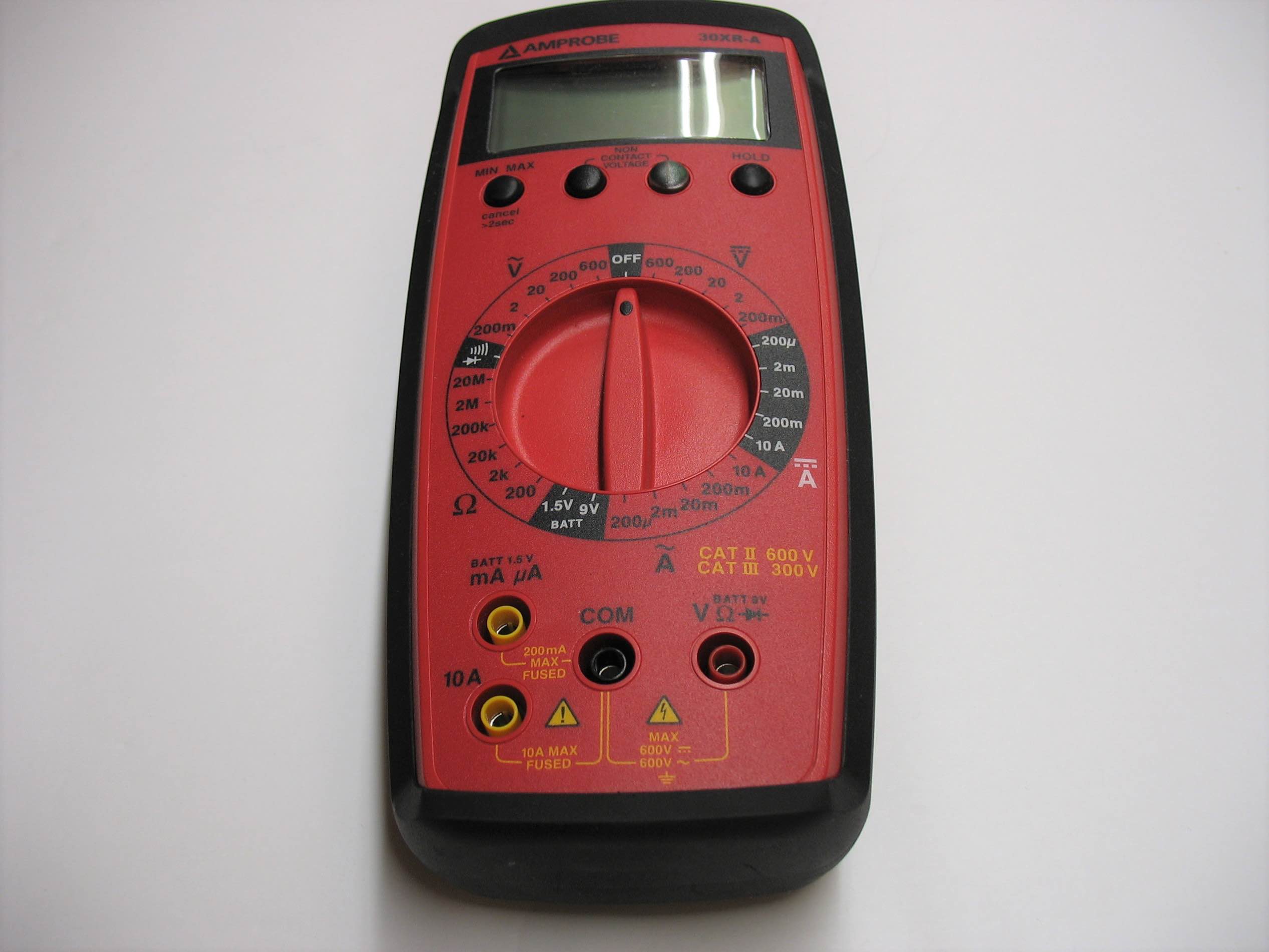
DC Voltage
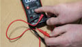
Reading a simple constant voltage from most digital multimeters is extremely simple - turn the dial to the DC voltage icon and place the test leads at two exposed circuit contact points, and a number appears. But this simple reading is only the very surface level of a function that is designed to be much more capable than a single reading.
On some meters, especially the older style of analog multimeter, most of the readings must be selected to read at the proper range. If you want to measure a specific voltage, you must select the appropriate value range. These are called ‘manually ranging’ meters in contrast to the common auto-ranging type.
Manual Range Selection
You must first determine what voltage you expect to measure, or at least close. If you have an industrial control system in front of you, 24 volts is the likely measurement. A small computer board might be more likely at 3.3-5 volts.
Whatever that target voltage happens to be, select the range with a value just above that number. Sometimes, the ranges might include: 1, 10, 100, and 1000 volts, or perhaps 2, 20, 200, and 2000 volts. In this scenario of testing a 24-volt system you must choose the 100 or 200-volt range, respectively.
If the range selection is too small in value, the meter will read ‘OL’ which means ‘Over Limit’. Some people say Over Load, which is an accurate description but implies a dangerous situation. Not true in this case - it’s not dangerous, simply above the limit. On an analog meter, the needle will instantly peg to the right side of the display. This is the same as ’OL’ on the screen.
If the range selection is unnecessarily large, for example, if you expect to read a 5-volt signal but you place the meter onto the 1000 volt range, it might show simply 5. You don’t have any way to know if that value is actually 4.6, or maybe 5.3 volts? Too large of a range will be a very inaccurate reading. On an analog display, if the full range is 1000 volts, a reading of 5 volts would barely even move the needle, and it’s hard to make a good judgment call when the needle has hardly moved at all.
Using the Range Button
Almost every meter will include either the manual range selection, or it will have a button labeled ‘Range’, but never both. This button is very useful for finding short circuits and troubleshooting parallel control components, although it is very often under-used.
In a set of multiple parallel Normally Open buttons, one might become broken, or shorted, or the spring inside may have failed to cause a constant connection. This is a difficult situation to troubleshoot because the voltage will always read 0, no matter which button failed. You’ have to remove them one by one and test each time to find the one in which one raises the voltage back to 24.
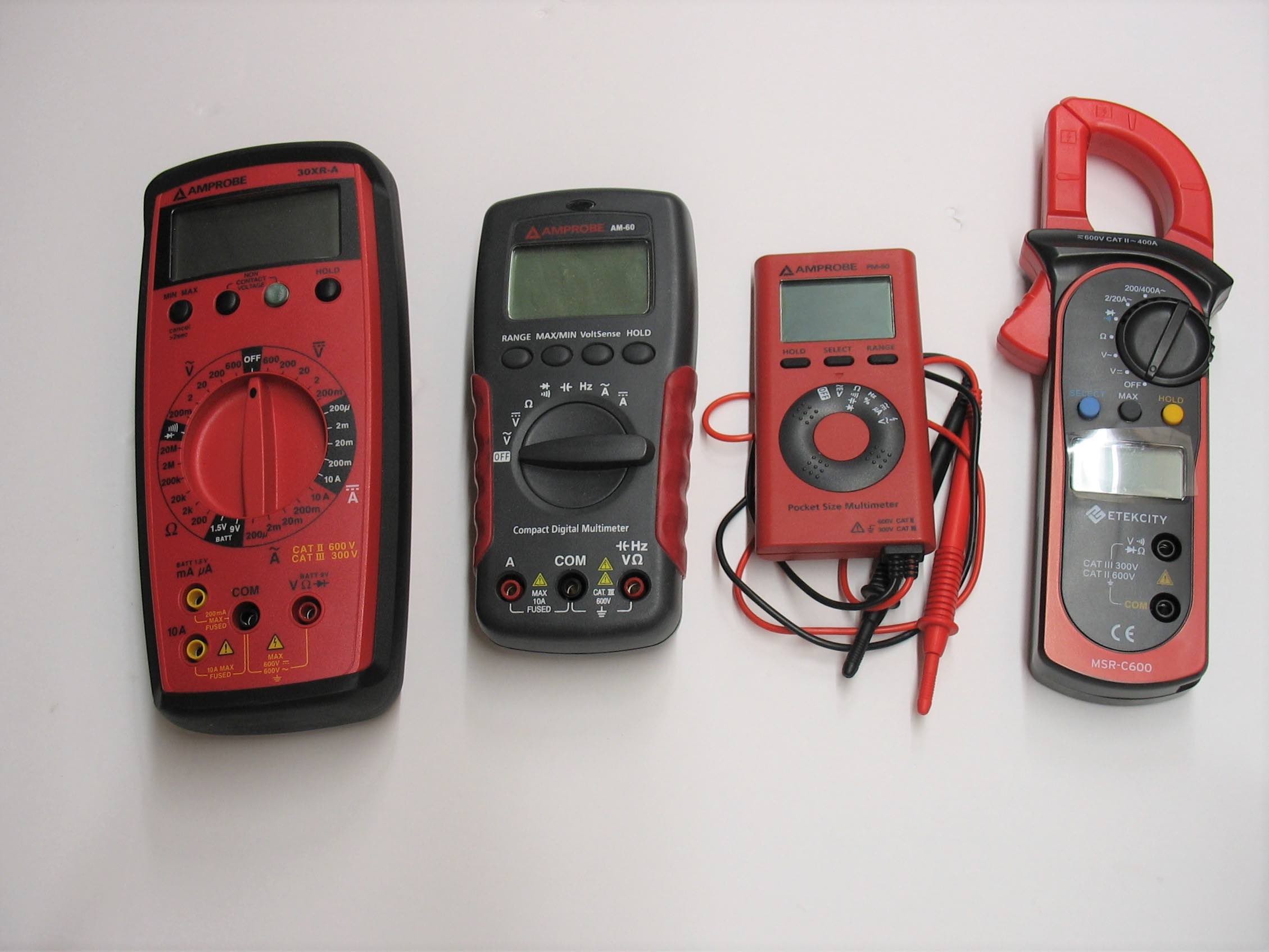
An array of multimeters displayed.
Instead, select the lowest range, or press the ‘Range’ button on the meter until the lowest range is selected. On some meters, there may be an mV function. This works as well.
Measure the voltage across the parallel circuit and you will likely see a couple of millivolts, no more. The auto range would always show 0 volts unless you manually make this range change. The millivolts are due to the tiny resistance of the switch contacts. Small, but not quite 0.
As you press the parallel buttons one at a time, the equivalent resistance (and therefore voltage) will reduce to half because now both the failed switch and the working one are closed. The small millivolts should get even smaller.
Once you finally test the failed component, the reading shouldn’t change - it was already closed, you don’t change it by pressing the button. Now you have found the failed parallel switch without having to remove a wire.
A short circuit is similar - you can locate the difference between the few millivolt drop of a functioning wire versus the virtually 0-volt drop of a short circuit.
Using the Min/Max Button
Most of the time, there is an ability to record a minimum or maximum voltage which is one step better than the simple instantaneous reading that shows ‘right now’ only.
This detection can measure the amount of voltage drop from power supplies when a large capacitive device turns on, or the flyback surge from an inductive load which has been turned off.
But it comes with a warning. This function is reading and storing voltage for a certain time period, with a certain time delay between readings. If the surge is too fast, you may miss it entirely. If it happens outside the reading time period, it also may miss the reading. If you expect a surge or drop to be happening on a very regular basis, you may need to turn to an oscilloscope. There are special industrial Scopemeters which are handheld devices that show visuals of changing voltages.
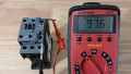
A digital multimeter, although this one does not automatically range through relative scales of each function, in other words, it’s non-auto-ranging.
This reading can be extremely useful when control devices appear to power off every now and then and you want to examine the cause. Place the meter on the input voltage line and let it record. If the Min voltage drops by just a few volts, it might be enough to turn off the controller, but the suspect is probably a large device powering on. If the voltage drops to near 0, then a short has likely occurred and the power supply has turned off momentarily to protect itself.
The symptom is the same in either case (controller briefly losing power) but the extra information can help make a better-informed decision to locate the cause.
DC voltage on a multimeter is a fairly straightforward reading. The extra knowledge of pairing that reading with the manual range selection and the min/max functions can bring more information and accuracy to the reading of voltage and ultimately, the solution to electrical faults.
Like using multimeters? We do too.
So much so that we published a downloadable eBook: The Guide to Digital Multimeters
Here are the other articles in this multimeter series:
- The Importance of Multimeters
- Understanding the Different Types of Multimeters
- How to Choose the Right Multimeter
- How to Measure AC Voltage With a Multimeter
- How to Use a Multimeter to Measure Current
- How to Measure AC Current Using a Clamp Meter
- How to Measure Resistance with a Multimeter