 Facebook
 Google
 GitHub
 Linkedin
Synchronized Motion for Servos | Coordinated Axes
Coordinating motion in three or more axes is a difficult manual process. For more advanced gantry or articulated robots, this motion type solves the complex calculation of a set of related joints.
The third and final installment in our synchronized motion dives into the world of coordinated motion control in Rockwell PLCs. The previous two forms of synchronized motion (gear profiles and cam profiles) could handle up to two axes at the same time, but coordinated motion can synchronize up to six axes at once.

Figure 1. A Festo collaborative robot that can be taught by moving the arm around. Image used courtesy of Festo
Creating a DIY Robot?
Similar to gear and cam motions, the coordinated motion function is designed to move multiple motors at once, so that all joints arrive at their designated positions at the same time. This means you could even create a custom six-axis articulating robot within Studio 5000. Follow along as we drive into the coordinated motion feature of Studio 5000.
Joint vs. Orthogonal Axes
Continuing the robot example, a normal industrial articulating arm uses six motors that are driven to a rotational angular value calculated within the controller. The final X, Y, Z, θX, θY, θZ tool position values we use in the robot program need to be reverse-engineered into those six individual joint positions, including any translation between tool and base coordinate frames.
When using Studio 5000 for coordinated motion, we first need to determine if the system is using revolving joint values or linear Cartesian values. I’ll use the Cartesian system in this example to reduce complexity.
Multi-Axis Setup
Setting up a coordinated motion system is more involved than any other synchronized motion system. The function blocks that actually move the servos need to operate in Cartesian coordinates, so if our system is a joint system, we need to use a transformation function block to generate the Cartesian coordinates.
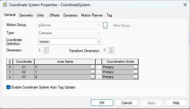
Figure 2. Configuration of the system properties. Image used courtesy of the author
The first step is to create a coordinated system. To do this, right-click on the motion group and choose New Coordinated System. A new tag window will open, with the required data type already populated, where you can create the coordinated tag name.
Open the Coordinated System Wizard to define the system properties. You will need at least two servos already configured. If you are using the emulator, you can use a maximum of three virtual axes. From this wizard, you can select how many axes are in your system, the geometry of the system, any offsets, the units of the system, and maximum motion parameters.
The PLC Logic Commands
For motion in a Cartesian system, there are three main function blocks: linear move, circular move, and path move.
- Motion Coordinated Linear Move (MCLM): moves a group of up to 3x linear axes from one point to another in either incremental or absolute units.
- Motion Coordinated Circular Move (MCCM): moves a group of axes in a 2D or 3D arc, with an end point and a defined radius or diameter.
- Motion Coordinate Path Move (MCPM): moves a group of axes to a defined x,y,z,Rx,Ry,Rz position, to be used in articular, SCARA, and delta robot types.
If you need to stop the motion, you must execute an MCS (motion coordinated stop) instruction.
In this example, I’ll use the MCLM (motion coordinated linear move) function block. The logic to drive this block will be very similar to how we have used the motion axis move (MAM) block in previous servo axis systems; the difference is that the MCLM requires three positional coordinates instead of one linear dimension.
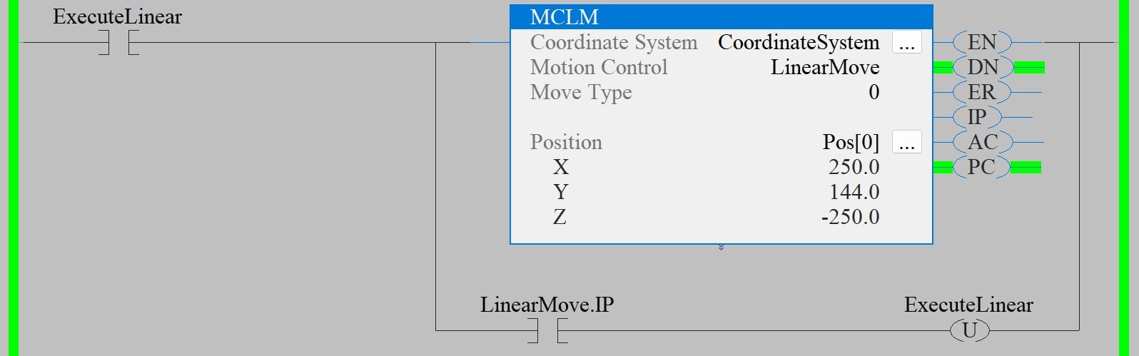
Figure 3. An example linear move using a coordinated system. Image used courtesy of the author
With every execution of the block, all three axes move to their defined positions. Once the move has started, you can update the positions for the next move, and when the first move is complete, you can execute the MCLM block again, unless you want to blend moves, in which case you don’t need to wait for the move to complete.
Coordinated vs. Other Synchronized Motion
With a coordinated move, the axes are not locked together, so you can still issue a MAM block on any individual axis, and only that axis will move. There are no additional blocks that need to be executed between coordinated motion and single-axis motion. All three axes will reach their designated positions at the same time, so some axes will move more slowly or faster depending on the difference between the positions.

Figure 4. A 3-axis gantry motion system. Image used courtesy of Festo
Typical Applications of Coordinated Motion
A common application for the coordinated motion blocks is a servo gantry. This type of system typically has three servo axes, all at right angles to each other, so there is no need to convert different coordinate systems. Simply add all three axes to a coordinate system into the motion group and use the linear motion control block to move between saved positions.
You can use standard jog logic for each axis to teach positions. Once the tooling is in position, save the X, Y, and Z positions into the Pos[x] array used in the MCLM. Now, when you command the gantry to each position, you will see smooth motion as all three axes move at the same time to reach the final destination.
This example merely introduces the capability of coordinated motion blocks from Rockwell Automation. There are far more functions and features that can be applied to different applications, and the best way to learn is to open the software and start programming.


The standard gantry has two axes only, which are defined as Master and Slave .