Facebook
 Google
 GitHub
 Linkedin
Synchronized Motion for Servos | Cam Profiles
Cam profiles are a great way of strictly controlling two servo axes to follow a predefined path. Follow along as we dive into setting up and programming an electronic cam profile.
A cam is a mechanical interaction where a shaft rotates an off-round, or lobed disk. The lobes are designed precisely so that a constant RMP of the shaft causes offset motion of a follower. It is a repeating cycle, but within a single revolution, there may be many small, irregular offsets.
In an electrical motion system, a single, constant RPM axis guides a second follower axis with offsets that act exactly like a mechanical cam.
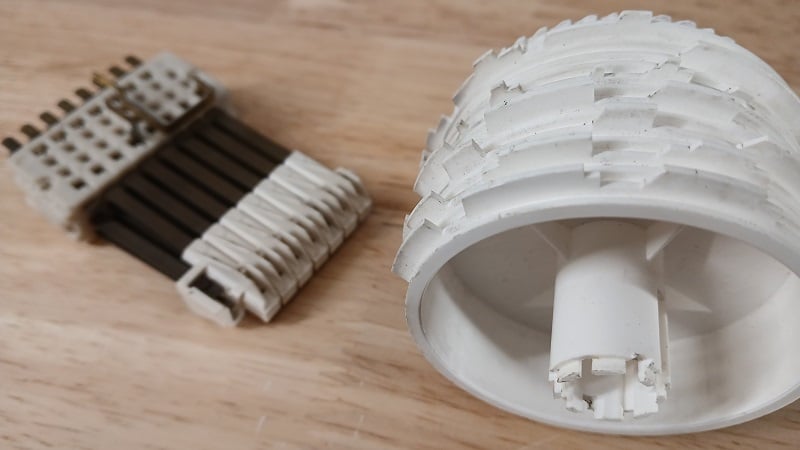
Figure 1. This cam engages electromechanical switches as the lobed drum rotates. Image used courtesy of Control.com
Cam Motion Profiles
A cam motion requires a Motion Axis Potion Cam (MAPC) block and a position cam profile. The profile is an array of values that relate the positions of the slave and master axes, determining how the slave axis should move in relation to the master axis. This profile can be created using the built-in editor or through a Motion Calculate Cam Profile (MCCP). The MCCP block allows the cam profile to be altered and then calculated programmatically within the logic.
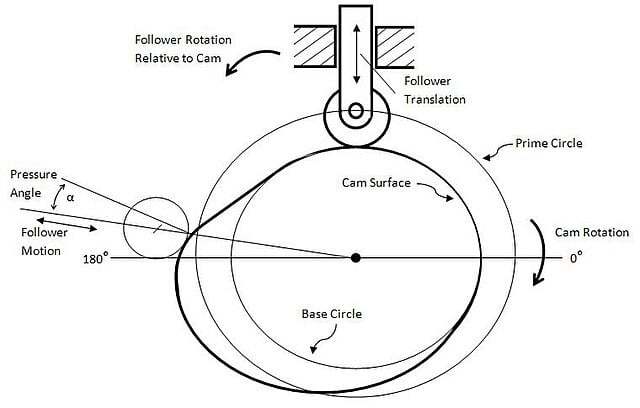
Figure 2. A graphical representation of a cam profile. Image used courtesy of Wikipedia
When the MAPC block is initiated, the designated cam profile is loaded, and the slave axis will be locked to the master axis, as set by the parameters. A Motion Axis Move (MAM) block will be needed to start the master axis moving. The MAPC block will evaluate each index of the position array and will move the slave axis to each respective position as the master moves through the cam profile.
The slave axis is driven to its specified position without any regard to maximum speed; both the master axis and slave axis reach the end positions at the same time. This means that if you have large movements between each index of the profile array, the slave axis will work very hard to reach its positions and could cause the system to fault.
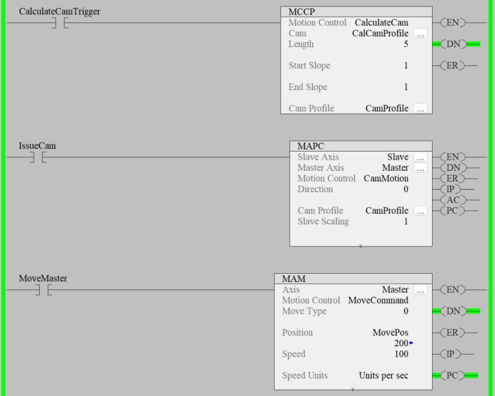
Figure 3. Establishing the cam interaction for a motion program. Image used courtesy of the author
Setting Up Parameters
Similar to the gearing motion block (as discussed in a previous article), you will need to define the master axis and slave axis, and the direction in the parameters of the MAPC block. A unique feature of the cam motion profile is the ability to set the block as continuous, one-time execution, or persistent.
- Continuous allows the motion profile to continuously run without having to re-execute the block. This is useful in rotary applications.
- Persistent will automatically engage and disengage the cam when the master axis travels inside the cam profile range.
- A one-time execution will engage the slave axis until the cam boundary is met. Once the master crosses the boundary, the MAPC block will need to be executed again.
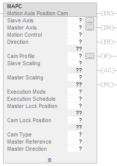
Figure 4. Full listing of MAPC parameters. Image used courtesy of Rockwell Automation
The next set of parameters defines when to execute the cam profile.
- The Execution Schedule informs the system if you are blending cam profiles, issuing a new profile, or if the cam profile will be used in a forward, reverse, or bidirectional motion.
- The Master Lock Position is the point at which, along the master axis, the slave axis will be locked to the master.
- The Cam Lock Position defines where you want the cam profile to start.
- Cam Type defines how to initiate new or replacement cam profiles, and whether to interpolate new positions immediately or to wait until the cam lock position.
- The Master Reference determines where you want the slave position generated from, either the actual position of the master or the commanded position of the master.
- Master Direction allows altering the direction of when to engage the cam profile. Either in the forward direction or only when the master axis is travelling in reverse. The bidirectional setting will allow the slave axis to track the master in either direction.
These parameters can be complex, allowing nearly endless configurations. It is best to simulate the code as much as possible before integrating it into a live system.
Adding The Logic
Once you have configured the MAPC block, you need some logic so that the MAPC rung will receive a transition from false to true. If you are running the cam in a one-time execution mode, you must add logic to reset the MAPC block to reactivate the cam profile.
After the MAPC block has been successfully executed, the master axis can be commanded to a position. When the master axis reaches positions defined in the cam profile, the slave axis will be automatically commanded to the position listed in the profile at a speed required to reach the final position at the same time the master axis reaches its position.
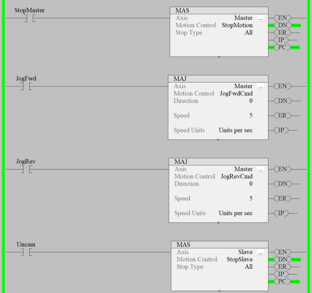
Figure 5. Examples of motion axis stop and jog commands. Image used courtesy of the author
Changing Cams
To change the cam during runtime, you will need to use an MCCP block. Ensure that the MAPC block is not in progress by issuing a stop command on the slave axis. You can now modify the positions in the cam profile for the MCCP block. After the position changes are complete, re-execute the MCCP block and execute the MAPC block to re-arm the new cam profile. Remember, the Cam Type parameter defines when/how the new cam profile will be implemented.
Developing The Cam Profile
Studio 5000 includes a cam profile editor that can be used to generate the motion of each axis. Insert cam segments into the editor to define positions for both the master and the slave axis. Ensure to use mostly cubic-type moves, especially for direction changes; a cam profile with only linear positions will fail to execute because it is being commanded to change velocity from positive to negative in a moment, and this is impossible. Adjust the start and end slope to ease the transition into and out of the cam profile.
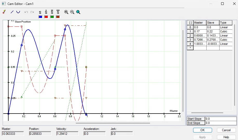
Figure 6. A cam profile that matches the master and slave axes. Image used courtesy of the author
Using CAD Software To Develop A Cam Profile
Developing a cam profile using the Studio 5000 software can only be done while offline with the controller and will require a download if it changes. It’s also hard to visualize the path each axis will take to arrive at its destination. Using CAD software with simulation packages, you can move the tooling through the process and record the positions. If changes need to be made, you can always resort to that CAD model and run the simulation again.
Cam Motion Is Not For Everyone
A cammed motion system is very complex and requires extensive simulation to ensure there are no interferences. If a path needs to change, it is not as simple as just re-teaching a few points. The benefit of the cam system is the speed and lack of sensing. If you have a pick and place system that uses a cam profile, that station is going to go through the motions regardless of whether the part is present or not, so there is less wasted time waiting for sensors, but more upfront simulation and engineering.
If you require a system similar to how a robot works, then you might want to look into coordinated motion profiles