Facebook
 Google
 GitHub
 Linkedin
Synchronized Motion for Servos | Gearing Profile
Synchronized motion has become an industry standard with robots, gantries, and pick and place automation. Follow along this three-part series as we discuss methods of synchronizing servo motors.
Most modern PLCs are capable of digitally synchronizing the motion between two or more servo motors. This synchronization allows designers to build motion systems that create coordinated paths, geared motion, and cam motion profiles. So, how do we configure a synchronized motion profile?
Over the next three articles, we will cover motion synchronization with gear, cam, and coordinated profiles using the common example of Allen-Bradley servo motors in Studio 5000.

Figure 1. A robot uses synchronized motors to perform work. Image used courtesy of Unsplash
Differences Between Gear, Cam, and Coordinated Motion
First, we must clarify the difference between a cam, a gear, and coordinated motion.
Gear - A gear profile is just how it sounds. Two motors run at the same time but are rotating at different speeds. Typically, this requires a master motor and a slave; the slave will rotate at a given fraction of the master motor. The ratio is defined in the motion properties.
Cam - A cam profile is similar to a camshaft in an internal combustion engine. This system includes a master axis that is rotating, and at some point(s) during that rotation, another axis moves a specific distance. The slave axis might move for the entire rotation of the master but with varying speeds, or for a portion of the rotation. The slave axis can also move in a positive or a negative direction. Cam tables are used to define when each axis moves and for how long.
Coordinated - Similar to the other motion profiles, this requires a master and a slave axis. Both axes have a set motion profile, and when commanded, both axes execute that motion. The slave axis will move at a dynamic velocity so that when the master reaches its position, the slave will reach its position at the same time. As the different positions for the slave and master change, so will the speed of the slave axis.
Gearing Two Servos
In order to gear two motors, you need to first decide which one is to be the master and which is the slave. The master is the motor that doesn’t alter its speed; the speed and position are taught and commanded through an MAM (motion axis move) command. The slave motor will follow at the desired ratio, so you won’t be able to teach the speed or the position of the slave motor when geared. You also need to make sure you will not be overdriving the slave motor with the chosen ratio.
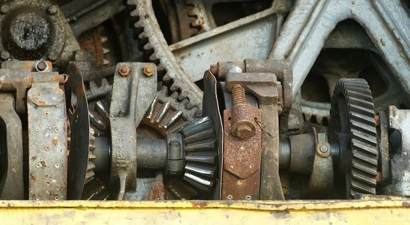
Figure 2. Image of gears that transmit motion and torque. Image used courtesy of Unsplash
The MAG (motion axis gear) block will activate the gear function. You can gear and un-gear motors whenever you choose, as well as control the acceleration and deceleration using the clutch parameter. The parameters for the gear application are set in the MAG block, along with specifying the master and slave axes.
Most of the parameter definitions are already contained in the help file, but here are some notes that might help first-time users.
Ratio vs. Slave and Master Counts
These parameters are used exclusively; if you have a specific ratio, you don’t need to use the counts. If you know how many master encoder counts you need per slave counts, then you can set them accordingly and leave the ratio parameter zero. The ratio needs to be a real value and is sign-specific, so entering a negative value will cause your slave axis to travel in the negative direction.
Clutch Parameters
In some applications, you need to gear and ungear in motion, similar to changing gears in a car. The clutch parameter utilises the acceleration and deceleration parameters set in the MAG block. When the MAG is engaging the slave servo, it will do it at a controlled pace, much like gently letting out the clutch pedal on a standard transmission car.

Figure 3. Automobile quality inspection using coordinated motion robots for smooth movements. Image used courtesy of Unsplash
Setting Up The Logic
The logic is very simple: determine when you want to gear the two servos. Some applications will require them to remain geared at all times, while others may remove the gearing at specific intervals.
Place a MAG instruction near the MAM instruction, and place any conditions in front of the MAG that your application requires. When the MAG rung is true, the two motors will move in a synchronized motion once the master axis is commanded. To ungear the slave servo, you need to issue a MAH (motion axis home) or MAS (motion axis stop) command. This will cancel the MAG command and unlock the slave servo from the master.
In the code example below, we have a simple linear axis that moves forward and backward 100 mm, specified in the MOVE commands, alternately placing 100 or 0 in the MasterPosition.
When the master axis is commanded to move forward, the slave axis moves at 1.5 times the speed of the master (indicated in the MAG) and therefore will arrive at an end position of 150 mm, exactly 1.5 x 100.
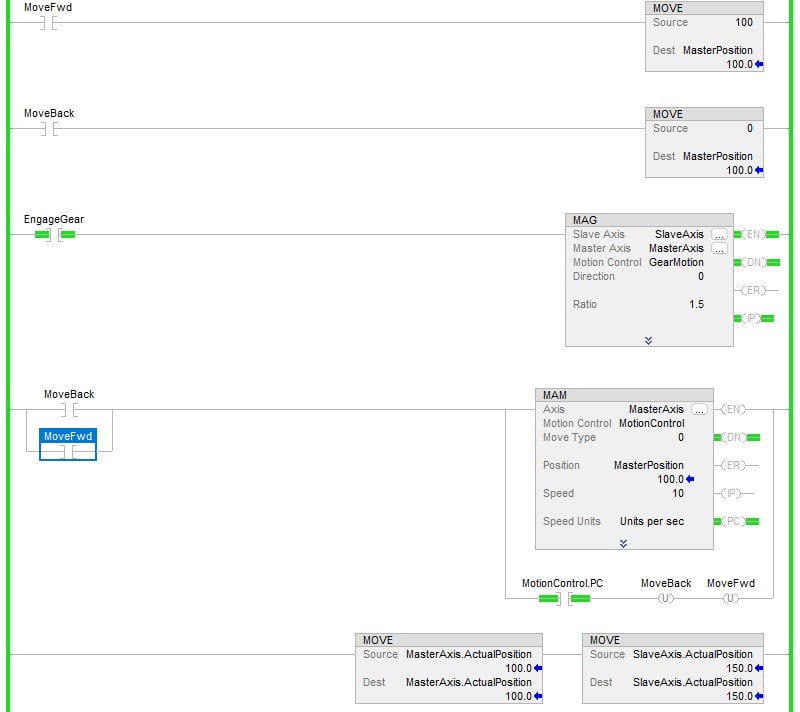
Figure 4. A sample program with a 1.5 gearing ratio. Image used courtesy of the author
If we change the MAG ratio to 10, the slave axis will move to a position of 1000 mm while the master remains at 100 mm. Changing the ratio to a negative value will drive the slave axis in the negative direction. For example, as shown in Figure 5 below, a -5 ratio value results in the slave axis traveling -500 mm.
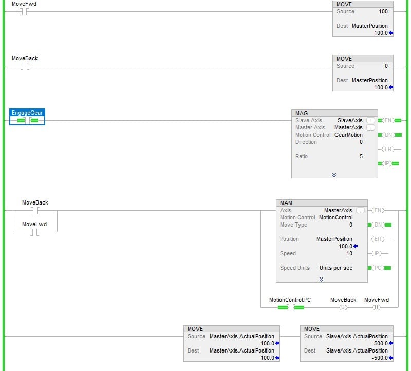
Figure 5. Modified program with a -5 gearing ratio. Image used courtesy of the author
Homing and Recovery
As a final consideration of this motion method, we need to evaluate the application and determine if both servos can be driven to their home position without being geared. Some applications will require a positional window where both servos need to be geared; this type of recovery can be more complex, so account for additional testing to make sure your slave gears with the master correctly.
As the system is recovering, you will need to make sure that the MAG block is enabled while the axes are moving through the window.
Featured image used courtesy of Adobe Stock