Facebook
 Google
 GitHub
 Linkedin
How to Identify and Use NPN Sensors
In this article, we will discuss the application and identification of NPN sensors, clarifying why they work and how to properly use them in a control circuit setting.

Most engineers and technicians envision sensors as being the device that sends process information into a control system such as a PLC, VFD, or similar. That thought process may be correct, but we should not get too locked into thinking about information flow and current flow in the same direction.
NPN sensors, as common as they are, turn the typical mental picture of current flow upside down.
When faced with the task of installing a new sensor or replacing one that has failed, a technician or engineer faces a decision. The polarity of most typical industrial DC sensors can be either PNP or NPN.
The PNP variety is usually easier to understand because it follows the conventional directional flow of current. Although NPN sensors still follow electrical principles, they can be more confusing.
Sensors are used in control systems to provide information to the controller, such as a PLC or motor drive. This input information is used to determine whether an input condition is true or false, or in other words, detection of current flowing or not flowing.
It’s important to remember that current will flow in a direction from positive to negative. This current flow direction does not have any correlation to the fact that information is represented as going ‘in’ to the controller.
Operation of NPN Sensors
To briefly summarize the operation of an NPN polarity sensor, when de-energized, current cannot flow through the load wire. But when energized by whatever sensing method is used (inductive, optical, etc), current flows through the load wire into the sensor which returns the current to ground.
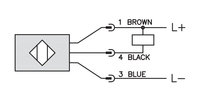
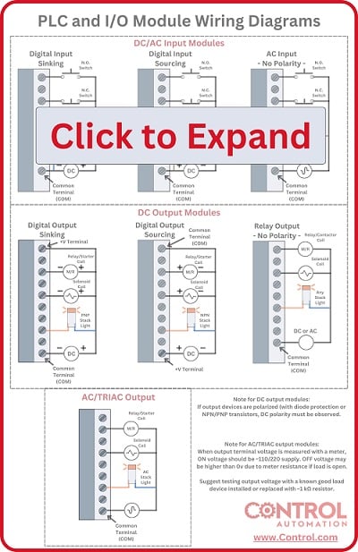
The wiring diagram for a typical NPN sensor. The load rectangle symbol connected to +V indicates a sourcing input module, requiring a sinking (NPN) sensor.
In order for an internal circuit to be completed, the current must be sent out from the control module (like the PLC input module) and into the sensor.
The concept of current flowing out of an input module is the main reason why NPN sensors seem to oppose the conventional directions of electrical flow. It’s important to remember that an input terminal on a controller only examines whether current is flowing, there is no inherent restriction as to which direction that current can flow.
A quick indicator as to whether an NPN sensor would be required is the common voltage to the input module.
If the common wire of a set of input terminals is connected to +24 VDC, that voltage will be present on each individual input terminal, which can be verified with a voltmeter. Therefore, this module is the source of the electrical current, referred to as a ‘Sourcing’ module.
In order for a sensor to be compatible with a sourcing input module, that sensor must allow current to flow in through the load wire and return the current to the ground. This is known as a ‘sinking’ style sensor, and must be used whenever a sourcing module is present.
In some device construction, the module will be fixed as either a sinking or sourcing mode, and cannot be changed. Other times, changing the destination of the common wire is the only change required to toggle between source and sink.
Wiring Diagrams of NPN Sensors
The input module’s common voltage may be identified by observing the common wire or by measuring the voltage at each input terminal. However, identifying the sensor’s polarity by simple observation can sometimes be more difficult.
In a separate article discussing PNP sensors, several representative device diagrams were shown to have a +V, -V as well as a Load wire. This load wire was attached to the rectangular symbol of a load device, which commonly would be the PLC input terminal. The opposite side of this load rectangle will connect either to power or to ground.
In the diagram of the NPN sensor, the load device will be shown to be connected directly to the +V source.
This connection represents the common voltage wire of the input module, which is also connected to the +V source. When the sensor is energized, the input module is the +V connection, and the sensor is the -V connection, completing the circuit.
The current can flow through the completed circuit and the input module detects the energizing of the sensor.

The wiring diagram for an NPN sensor with both Normally Open and Closed outputs. The load device connecting to +V shows that both outputs are of NPN polarity.
To test the polarity of an NPN sensor, remove the load wire from the input module. With the voltmeter measuring the open load wire observe the voltage as the sensor energizes. An NPN sensor will swing between ‘open’ and ground, which would likely show 0 volts nearly the entire time, regardless of the energization state. A PNP sensor, in contrast, will toggle between 0 and 24 volts.
Construction of the NPN Sensor
The internal construction of an NPN sensor uses the transistor with the same name, based on the N-P-N layer construction of the semiconductor. Inside this transistor, when the base pin is given a small current, such as from the actual sensor transducer, a larger amount of current flows from the Collector to the Emitter.
The load wire going to the PLC is connected to the base. When energized, current will then flow from the PLC into the Collector, and return to ground through the sensor.
In this way, the current enters the sensor from the load wire and returns to ground, the characteristic operation of the NPN sensor.
NPN Sinking sensors are necessary when the interacting input module is of the sourcing polarity, that is, voltage is continually supplied to the input terminals. When the sensor is energized, current flows from the module to the sensor and returns to ground.
Diagrams used courtesy of Automation Direct.