Facebook
 Google
 GitHub
 Linkedin
Tutorial: How to Set Up a Light Curtain
Learn how to align and configure the parameters of a light curtain using a send/receive pair of SICK deTec4 light beam curtains and the new DCM4 extension module for advanced operating modes.
Safety devices can be a difficult topic of conversation in the field of control system automation. This is mainly because the risk assessments and regulations are so strictly controlled that a safety misstep can lead to significant personal or financial hazards.
After conducting those risk assessments and following the rules, next comes the step of installing and configuring the safety devices.
In this article, we’ll take a look at setting up one of SICK’s newest safety light curtain extension modules, paying particular attention to custom muting and blanking applications in the Safety Designer software suite.
Require Hardware and Software
There are several critical elements to this project, and a few optional ones depending on the intended use.
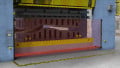
First, we will use one pair of deTec4 sensing/receiving light curtains. This installation uses the 900 mm version. These deTec curtains require a set of system plugs (like these) that receive M12 connectors for extension modules and power.
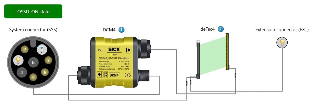
Figure 1. Hardware layout: system connector for power and reset signal, DCM4 extension module, and deTec4 light curtain pair.
Speaking of extension modules, this is an accessory set that connects mainly to the receiving light curtain, but sometimes to both. These modules allow more advanced detection modes than simple beam-breaking with OSSD safety outputs. Examples of these modules include the DMM4 and the DCM4; the latter will be used in this project. Communication modules also allow light curtain diagnostics through IO-Link.
Most of the connections use M12 extension cables, some 5-pin and some 8-pin. I recommend at least one M-F extension and one F to pigtail cable for power. Be sure to note if your cable has different color pinouts than standard M12.
Other hardware that will be necessary is a 24 volt power supply, and one or more pushbuttons and sensors. For object pattern detection, a reset button will be needed. For muting operations on a conveyor, two sensors are used in a dual cross-beam pattern or an across-the-line L-muting pattern.
You’ll also need a data-rated USB cable. On the PC side, download and install the SICK Safety Designer software.
Connecting the Light Curtains
When using the light curtains directly with no extension module, you can power them by connecting the M12 system connection cables to power. In typical fashion, the brown wire is for +V and the blue wire for -V.
- Once again, if you have a non-standard cable color, verify the pin numbers first!
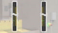
If using an extension module, like the DCM4, plug the appropriate M12 connectors into the extension module, matching the symbols in the image below.
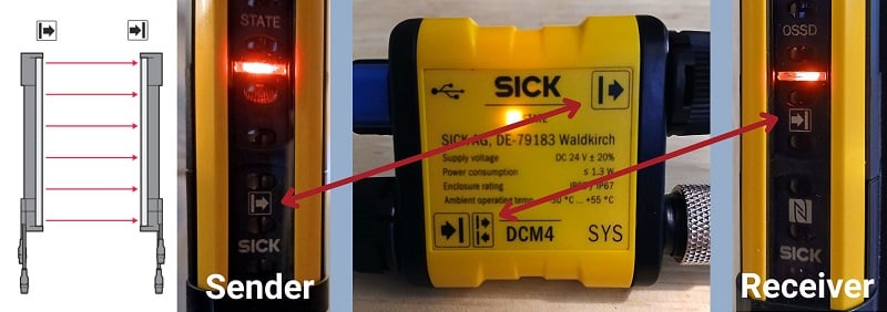
Figure 2. Matching sender and receiver symbols.
The connector labeled SYS is the system connector for power and user-assigned signals for various applications. The SYS connector is an 8-pin M12, and once again, the brown wire supplies +V and blue is -V.
Once the connections are made, you can evergize the power supply.
Configuring a Fixed or Floating Blank
Connect the USB to the DCM4 and the computer and open SICK Safety Designer.
Start a new project, navigate to the Configuration tab, and select Search on the right sidebar. Make sure the DCM4 is powered on and connected, and it should appear in the list, noting that it is not currently added to the project. Drag it into the workspace to add it.
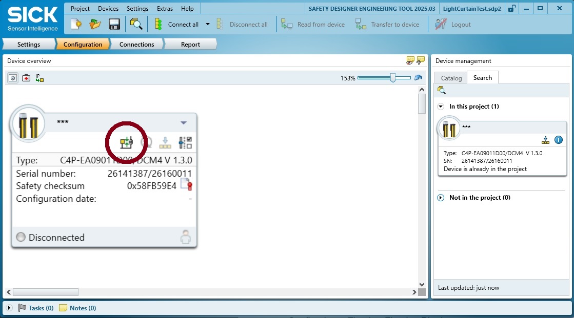
Figure 3. Hardware added to the project.
When re-opening this project in the future, you can connect to the module using the Connect Device button, which is under the red circle in the image.
Just to the right of that button, open the Device Configuration menu.
Here we can find the configuration for blanking, which can be used for various situations.
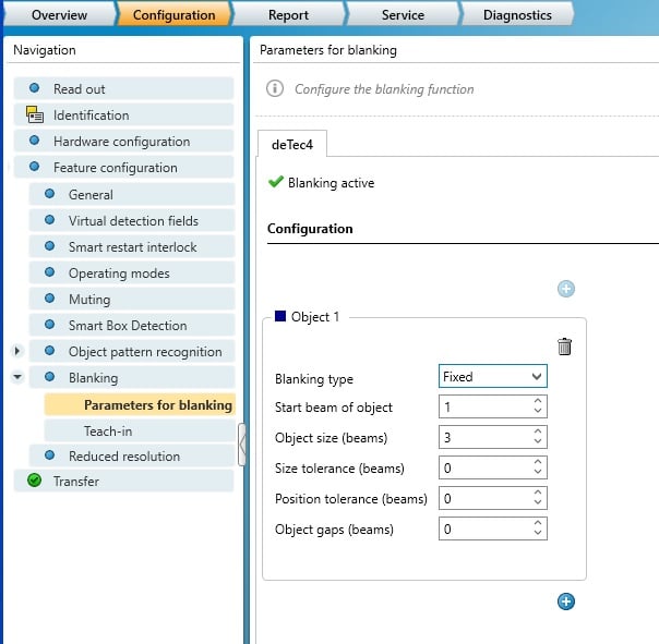
Figure 4. Blanking
If we activate blanking, we have two options for setting up the situation.
We can add a few different zones for fixed and floating blanking. This may be useful when sticking metal into a press brake, and after it’s been bent once, perhaps one of the bends will enter the field again in a second spot. So we may need two blanking regions. We can determine where on the light curtain the blank is expected to be located, and how large it will be. If it might move around (human error), we can add one or two beams of tolerance
We can also teach in the blanking, which means to insert the object(s) and intentionally block a few of the beams, while activating a teach-in button, then saving that setting. We can customize the tolerance after that, just like before.
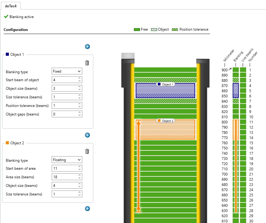
Figure 5. Two blanking objects in the field.
Muting the Sensor
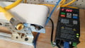
To use the muting feature, the system must detect the object's presence to mute the sensor, then, after it leaves the field, re-energize the signal. Detecting the object’s presence means using sensors across or before the sensor beam path. In the hardware configuration menu, there must be a selection of which pins are receiving the detection signals, which are set up in the hardware configuration menu.
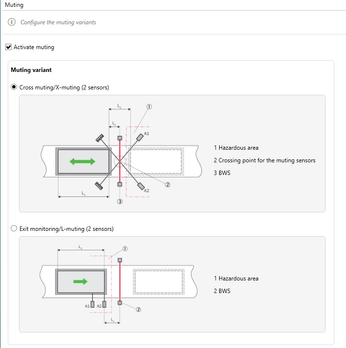
Figure 6. Choosing a blanking sensor setup.
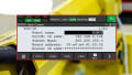
Once the pattern is selected, the details of the muting must be configured. The muting parameter menu requires details of the sensor signals to be completed, and requests timeout instructions for any time delays between the two sensor triggers, and a total elapsed time (like on a stopped conveyor belt) before the muting is automatically turned off and the sensor is returned to normal safety operation.
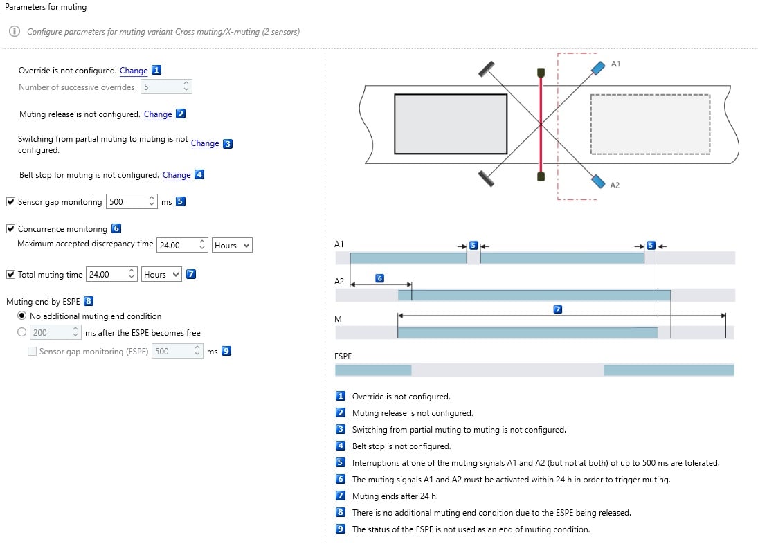
Figure 7. Muting parameters.
Remember, muting means temporarily turning off the safety sensor, so it must be carefully configured to be unmuted again as soon as possible.
Safety Sensors
This article represents only a small selection of the options available in safety light curtain configurations. Every situation calls for careful risk assessment, and safety isn’t something that can be addressed so as to make it as ‘easy’ as possible. And for that reason, it’s an element that should be planned early in the design phase.
All images used courtesy of the author