Facebook
 Google
 GitHub
 Linkedin
The Guide to Commissioning a Variable Frequency Drive (VFD)
Learn how to set up a VFD, from initial unboxing to configuring the network parameters necessary to drive some simple motion from a PLC.
Setting up a VFD is a somewhat simple task compared to some types of motion. There are various modes of operation, including local control, hardwire I/O, and network. In this article, we’ll discuss the setup of a new VFD, including jumping-off points for each of these previously mentioned control methods.
Throughout this example, we’ll look at a DURApulse GS20 drive with an additional Ethernet card and run it from a Rockwell CompactLogix PLC.
Unboxing and Safety Precautions
The first step is disconnecting the main power that will provide the supply voltage to the VFD, since exposed wires will be in use. Depending on the model, this may be 1-ph or 3-ph voltage. Also, turn off any external DC power supply if it will be used to make connections to local I/O devices.
Inventory
Remove the VFD from the packaging and make sure you have all the necessary components. This includes mounting hardware, ground screws, and any jumpers that might be needed for safety (STO) input terminals.
If you plan to use a network, be sure you have the right network card and connector cable, assuming the network port isn’t embedded in the VFD (those are really convenient).
You will almost certainly need a Phillips screwdriver for the power connections and most likely a small flat-head screwdriver for any I/O terminals.
Wiring
Two wiring elements are absolutely necessary, no matter how the VFD is used: the power input and the motor output power.
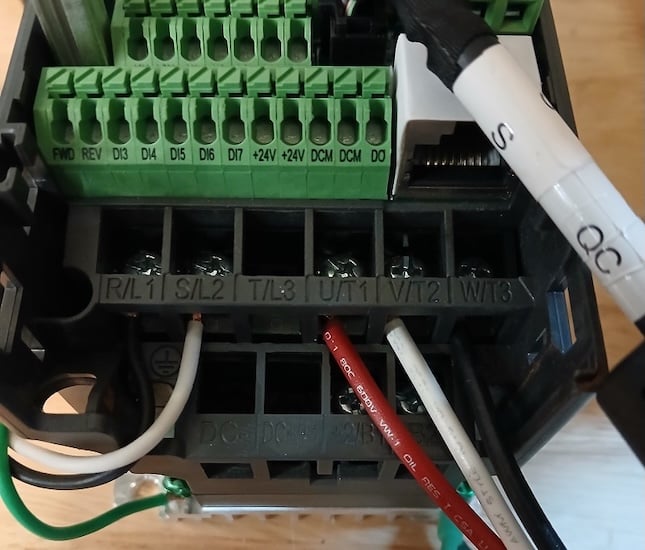
Figure 1. Input (left) and output (right) wiring.
After that, there are a couple of optional wiring arrangements based on the drive mode.
Input Power Wiring
Since many VFDs have 1-ph or 3-ph supplies, there are a few scenarios for input wiring connections. Different manufacturers label the terminals differently, so the following table lists many common terminal label formats and what should be connected to those terminals.
| Input Type | Terminal Labels | Function |
| 1-Phase, 110/120 V | L1 / L2
R / S U1 / V1 |
Line 1 / Neutral |
| 1-Phase, 220/240 V | L1 / L2
R / S U1 / V1 |
Line 1 / Line 2 |
| 3-Phase, all voltages | L1 / L2 / L3
R / S / T U1 / V1 / W1 |
Line 1 / Line 2 / Line 3 |
Note: Reversing two of the three input phase wires will NOT reverse the motor direction. That happens after the VFD output.
Ground terminals will be marked and indicated for the ground connection. This may be an additional terminal or a green screw on the body of the VFD.
Output Power Wiring
VFDs only supply current to 3-phase motors. Therefore, there is only one scenario for output wiring. Three-phase outputs will be labeled with only a couple of common schemes: T1/T2/T3, or U/V/W.
Once again, the motor connection will include a green indicated ground.
Control Wiring
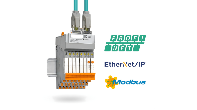
If the VFD is controlled over a network, as many are these days, the VFD may require a network add-on card. The network card connects to the VFD body with a small multi-pin cable, which will vary slightly between manufacturers.
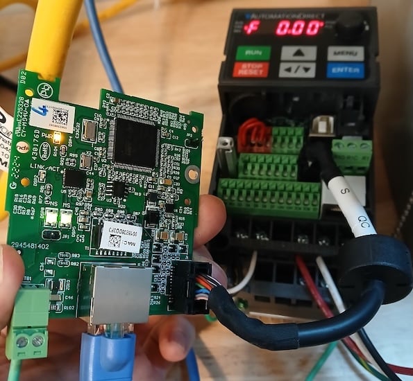
Figure 2. A special cable attaches the network card to the VFD.
If the VFD is controlled by local I/O, either pushbuttons or a primitive interaction with the PLC digital I/O, then the wiring connections must be established. This is a bit harder to address in a single tutorial. Still, most manuals will provide a comprehensive list of control wiring examples along with any switchable settings for sourcing/sinking polarities.
Parameter Setting
Parameters determine where the drive receives its commands and how to respond to them.
To properly commission the drive, a few categories of parameters must be examined. Consult the manual for exact parameter numbers and the method of changing them.
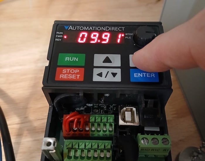
Figure 3. Parameters determine how the VFD operates.
Motor Parameters
Defining the motor allows the VFD to monitor the voltage and current to prevent some faults and provide corrective alerts. The data to be entered is usually read directly from the motor dataplate.
Ramp Parameters
No matter the commanded speed, there are many acceleration, deceleration, and certain skip frequency parameters to address.
Command Source Parameters
Drive commands can come from the local pushbuttons, from digital inputs, or from a network port. The speed command can often come from a course different from the start/stop commands.
The parameters in this category include not only the source of each command, but also the function of certain digital inputs, outputs, and preset speeds.
Network Parameters
Although the source of commands is set in the previous section, the specific network configuration is set, including IP addresses, speeds, and communication timeout information.
Fault Parameters
Finally, the drive must respond properly to various problematic conditions, depending on the severity within the machine.
Driving the VFD
If the commands are set to local control, you are finished. The drive should respond to button presses and the potentiometer on the front of the VFD.
If the command source is set to local I/O, the process should also be finished, as long as the wiring was set up successfully in the previous ‘wiring’ step.
In the more modern case, the VFD is networked to a PLC. This process requires a couple more steps.
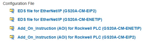
Figure 4. This drive includes downloads for the EDS and AOI files for a Rockwell PLC.
You must find and download an EDS, or electronic data sheet, for an Ethernet device. We already have a tutorial for installing those files. PROFINET and EtherCAT have similar data sheets. Once the data sheet is installed, a new VFD with a unique name and network address can be added to the project.
To more efficiently use the devices, some manufacturers will provide add-on instructions (AOIs), which are simple function blocks that address start, stop, speed, acceleration, directions, and other common instructions. The instruction is associated with the name of the drive when it was added to the project.
Commissioning Motor Drives
Like PLCs, each brand of VFD has unique features. However, like PLCs, the general strategy is the same, so many steps can be shared between all brands. If you have connected more than a couple of VFDs, you’ll probably find easy success with nearly any drive you encounter in the future.