Facebook
 Google
 GitHub
 Linkedin
Learning Some BASIC Programming in a PLC Environment
Use the analog capabilities of a TRi PLC to read a distance sensor and create a custom function that triggers events using integer data types.
Learning to use a new kind of PLC always requires two angles: the hardware (wiring connections) and the software (language and functions).
In this article, we’ll explore analog inputs and programming of some custom functions for the TRi PLC. A previous article provided a basic intro to TRi PLC digital I/O and setting up the i-TRiLOGI IDE. Now we can focus on a few more advanced features.
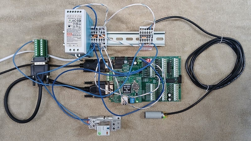
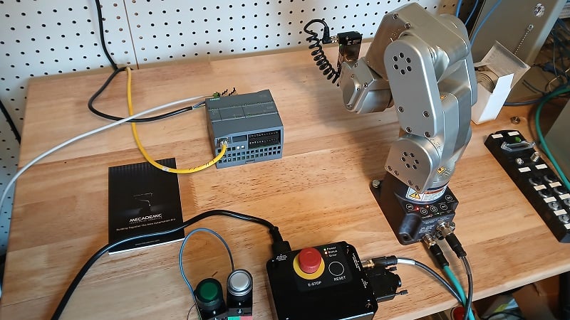
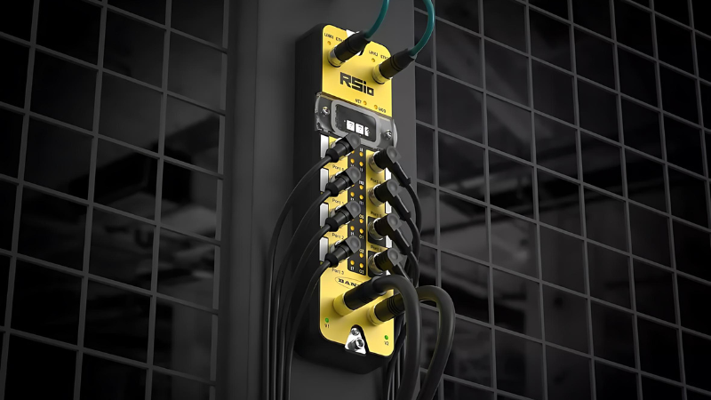
Figure 1. Finished project with extension cable for analog I/O.
Analog Input Wiring
Before discussing wiring, there are two noteworthy aspects of the handling of analog I/O in the TRi PLC platform. One is the fundamental difference between the two groups of input terminals, and the other, closely related, involves an adaptation for 0-10 V sensors.
Analog Input Groups
There are eight analog inputs in this PLC. Inputs 1-4 are known as high-impedance, meaning that the input resistance of the terminal is on the order of tens of megaohms (MΩ). For load devices that form a voltage divider between +V and ground (like a potentiometer), the high resistance of the input will not affect the voltage divider in any appreciable way at all.
Inputs 5-8 are low-impedance, or specifically, around 20 kilo ohms (kΩ). Some analog devices are configured for low-impedance inputs, but even standard sensors will work well if paired with an appropriate limiting resistor.
Converting 10 V to 5 V
Once we have picked an input group to use, we need to settle on a strategy for connecting our sensor. This sensor provides a 0-10 V output, but the inputs are designed for 0-5 V. On the surface, this may seem inconvenient, but it actually allows greater flexibility because it’s much easier to knock 10 V down to 5 V than it is to double the voltage with an amplifier circuit.
If we choose inputs 1-4, we will create a voltage divider using a pair of 10 kΩ resistors. If we use inputs 5-8, we will need to place the sensor output in series with a resistor equal in size to the 20 kΩ of the input. Conveniently, we can use 2x 10 kΩ resistors in either scenario.
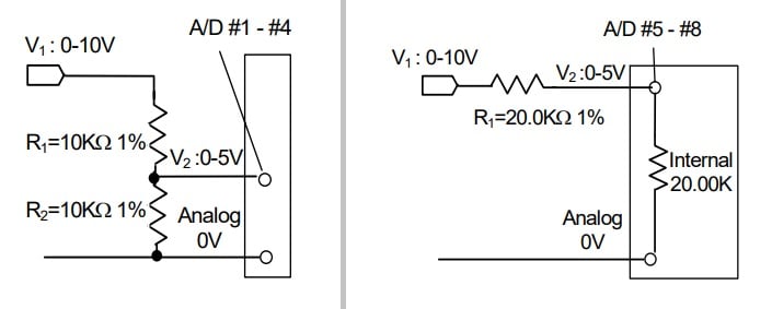
Figure 2. Resistor combinations for inputs 1-4 (left) and inputs 5-8 (right). Image used courtesy of TRi PLC
For this experiment, I purchased an extension cable and a breakout board for the DB-15 connector that contains the analog I/O. The analog ground 0 V signal on pin 9 is internally connected to the power supply 0 V, so we only need to supply the 0-5 V signal to the pin. I’m using analog input 1, on pin 8, and an ultrasonic distance sensor.
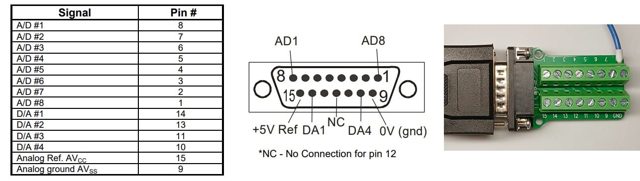
Figure 3. Analog signal pins. Pin 8 (A/D 1) is used for this project.
Programming the Inputs
We’ll break the programming into two steps.
First, we will read and store the values of the analog inputs, learning how to read one or multiple within a single command. Next, we’ll use those stored values and an inequality statement to energize digital output terminals.
Storing Analog Values
One difference between TRi PLCs and other brands is that the analog inputs are not automatically obtained on a cyclic basis. This difference saves processing time but does add the extra step of forcing the user to read one or more inputs before they can be monitored.
Set up a new rung of logic, with a single contact as an input on the left side.
When prompted to choose a variable value from the I/O table, use the red arrows to go across to ‘Special Bits.’ From this menu, you can choose a clock bit that reads the values as often as needed, reducing processor burden. If you don’t need to refresh the analog values more than a few times per second, you really don’t need them refreshing once per each ladder scan. I will choose Clk:0.5s for a half-second refresh rate.
To read and store the analog values, we will create a custom BASIC function by adding a coil output to the rung and choosing dCusF,
Note: There are two ways to define a custom function, CusF and dCusF. The difference is that CusF is executed every scan in which the ladder logic is true. The dCusF is only executed on the first scan in which the ladder logic is true. Sort of like asking this question: “Do you want to execute this instruction each time a button is pressed (dCusF)? Or do you want to execute this instruction the entire time this button is being pressed (CusF)?”
Inside our dCusF, we will build a short script in BASIC that will read all 8x analog inputs and convert them to a scaled value before storing them in registers. This way, the values can be used in subsequent instructions without requiring the controller to read the analog values over again before the next 0.5 s clock cycle.
We’ll call our dCusF AnalogRead, and the function editing screen will appear. A FOR loop will increment the I value from 1 to 8 for each of the analog inputs. ADC(x) will read each analog input, which returns 0 to 4096, and scales it to a value of 0 to 5000, and then places it in the matching DM[x] register. For any other scaled value (like a temperature, or a distance in mm, for example), change the yellow highlighted value.
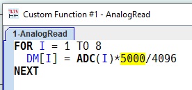
Figure 4. Custom function to read analog values.
Once this program is downloaded, open the menu Controller -> On-Line Monitoring, and the 8x analog values should appear at the top. If the sensor is connected, that input should reflect a value from 0 to 4096, since it displays the raw ADC value, not the scaled DM[x] value.
Energizing a Digital Output
Since we now have access to integer values, we can use a comparison to choose a threshold for triggering a digital output. In many other PLC IDEs, comparisons are provided as function blocks, but because they are quite simple, they are left to user-defined functions in the i-TRiLOGI environment.
In the next rung of the program, we will use the same Clk:05s input, since there is no point in updating the output any faster than we are checking the inputs. To this rung, add a second custom function dCusF.
I gave this function the name SetOnLimit and added the following code:
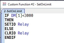
Figure 5. Custom function to energize outputs around a threshold.
Here is a brief explanation of the code:
- DM[1] is storing the value from analog input 1. IF this value is less than 3000, then we use an I/O instruction.
- In this language, SETIO and CLRIO will turn an I/O terminal on or off.
- If the value is less than 3000, we will energize our digital output named Relay.
- Otherwise (greater than or equal to 3000), the relay will turn off.
- ENDIF is the BASIC instruction that ends an IF statement.
Testing the Code
If the code is working properly, an object close to the sensor will energize the relay, but moving it away will turn off the relay.
This project provided a few examples of BASIC function programming, but a full list of commands is provided in the documentation. Download the zipped folder that contains the i-TRiLOGI Programmer's Reference for an entire list of the commands available to the programmer. This PLC platform is simple, but it has a few hardware and software surprises that can be easily handled with a little investigation and preparation work.