Facebook
 Google
 GitHub
 Linkedin
Advanced Boolean Logic with FBD PLC Programming
Learn about more advanced Boolean logic functions, including truth tables, Schmitt triggers, and multiplexers that can be implemented in a PLC function block programming environment.
Making basic functions using ladder logic, structured text, and function blocks is easy. These basic functions usually include series AND logic, parallel OR logic, plus various timers and counters. However, a few advanced logic functions prove useful for custom situations where the basic setups just aren’t sufficient.
What are Advanced Boolean Functions?
Boolean logic is the science of using 1 and 0 (on and off) values fed into mathematical formulas that produce meaningful, predictable results. This is perfect for PLCs, since most sensor and actuator I/O use a 1 and 0 on/off format.
Basic Boolean functions include AND, OR, and NOT, plus a couple of simple combinations, and these logic gates have been discussed in a previous article. Anything beyond these basic gates could be considered advanced, but we’ll focus our discussion on a few that can be helpful in certain situations and are often found in FBD PLC programming environments.
- Custom Truth Table Functions
- Multiplexers
- Pulse Generators
- Schmitt Triggers
Each example will show the function used in an FBD programming environment. Not every example will include a ladder logic equivalent, since some of these functions are somewhat difficult to convey in a simple screenshot example.

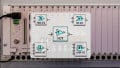
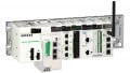
Figure 1. The Crouzet Millenium Slim PLC in a simple setup with 4x inputs and 4x outputs.
Truth Tables for Custom Actions
Before explaining the truth table in its Boolean form, imagine a PLC with 4x digital inputs. There are 16 different possible on/off combinations for these 4x inputs. We need to determine if a certain output relay is on or off for each combination.
In ladder logic, this can be accomplished with parallel rung branches filled with NO and NC contacts. “If Input1 is on, and Input2 is on, and Input3 is off, and Input4 is on, then turn on the relay, OR, if Input 1 is off, Input2 is on…” and so on. You see the point. You would need a branch for every combination that should cause the relay to turn on.
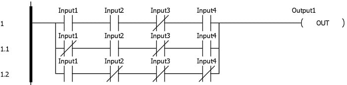
Figure 2. Three sample lines in a ladder logic truth table.
A truth table accomplishes this same function in a concise, tabular format. 16 rows of 5 columns, 4x for the inputs, and 1x for the output relay. Each row represents one of the possible combinations, and you only need to determine whether the output should be on or off. In FBD programming, the truth table can consolidate a lot of code into a very simple function block.

Figure 3. An FBD example of a Boolean truth table (has the same output as the ladder in Fig. 2).
Multiplexers/Demultiplexers
A somewhat oddly named integrated circuit (IC) is shortened to the mux and demux, and its job is to select between several signals or to send a signal to one of multiple destinations.
The mux has 4 or 8 input signals and 2 or 3 selector inputs. With two selector inputs, there are four combinations: 0-0, 0-1, 1-0, and 1-1. Depending on the current state of the selector inputs, one of the inputs will be routed to the output. Think of it like the channel selector on your TV. Select the right station, and that image will be displayed on the screen.

Figure 4. An example of a multiplexer function. This one is a 2-channel mux with two inputs (I2 and I3) and one selector input (I4).
A demux is the opposite. A single input can be distributed to one of 4 or 8 outputs, also chosen with the selector inputs.
Pulse Timers
Most PLC timers use a control input to turn on after a preset time (on-delay), or to delay a preset time before turning off (off-delay). However, the digital logic world provides us another useful timer called the one-shot, which is not to be confused with PLC one-shot commands, also called a monostable multivibrator. An input trigger causes the timer to pulse on for a short, configurable time, then turn back off. Unlike the TON, it energizes immediately and begins timing immediately, unlike the TOF. So it’s a useful third kind of timing tool.
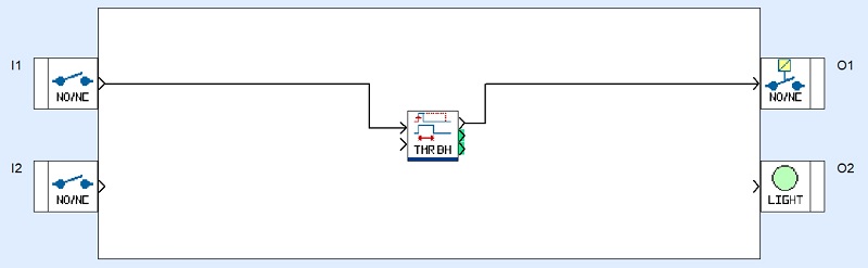
Figure 5. A monostable multivibrator, or single pulse generator.
Schmitt Triggers
The Schmitt trigger is a blend of both digital and analog. A logic gate turns a fluctuating signal into a smooth binary output. Imagine you had a distance sensor and the target value was 100 cm. However, you wanted a bit of a window so that if the target were exactly 100 cm, it wouldn’t sit there toggling on-off-on-off.
This function and the integrated circuit from which it was named, the Schmitt trigger, accept an analog input with two other inputs (variables or constants), a high and low window, to establish the point at which the output signal should turn on, and a lower point at which it should turn off.

Figure 6. The Schmitt trigger has both a signal input and threshold inputs.
What Can You Build with Logic?
Each IEC programming language has its strengths and weaknesses. FBD has the advantage of linear wiring that behaves exactly like circuit traces, so it makes sense that most functions look exactly like their integrated circuit counterparts. This arrangement is perfect for many of these digital logic combinations and is worthy of more detailed exploration.