 Facebook
 Google
 GitHub
 Linkedin
Boolean Logic for Ladder Diagrams
Ladder diagrams, or ladder logic, is a popular programming language used for PLCs. Programmers can utilize boolean logic as a base for their ladder diagrams. Learn the basics and structures for boolean logic.
Every device controlled by a central processing unit (CPU) understands instructions in the form of 1’s and 0’s. This statement is commonly repeated through many fields of computer science and electronics, yet it can be difficult to understand in a meaningful way for engineers and technicians who work with digital devices on a daily basis.
For those familiar with any brand of PLC, the “boolean” or “BOOL” data type is the core atomic data type used to generate tags in a database. But this concept applies to far more than simply the tag listing, and the ability to execute instructions based on boolean logic combinations is an important concept to understand.
The bool—also called “bit”—is unique in data structures in that it cannot be broken down into smaller pieces. All other integers, strings, and various types can be simplified into the individual bits of which they are made (e.g., a 16-bit integer really is just 16 bits). So that means that we can work with bits by themselves one at a time, or we can deal with chunks of bits altogether.
This is the difference in programmable logic controller (PLC) instructions between discrete structures, like two Normally Open contacts in series AND logic, versus two integers matched together with a Bitwise AND command. Without some understanding, this can be confusing.
Discrete Boolean Logic
First, and most simply, we can place simple discrete instructions onto a ladder logic rung, creating a set of true/false combinations to activate output coils.
Consider the following example ladder diagram in figure 1.
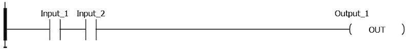
Figure 1. An example ladder diagram showing two inputs in a series leading to the output.
In this diagram, two inputs are placed in series leading to the output. Since ladder logic, as indicated by name, is logical, we should be able to express the statement in plain English. “Input_1 and Input_2 must both be TRUE in order for Output_1 to become TRUE”. In this statement, the use of the term AND indicates the logical instruction.
To turn the comparison to a setting a computer programmer would better recognize, the C++ code would be as shown in figure 2.
bool Input_1 = 0;
bool Input_2 = 0;
bool Output_1 = 0;
void loop () {
if (Input_1 == true && Input_2 == true) {
Output_1 = true;
}
else {
Output_1 = false;
}
}
Figure 2. Same logic as figure 1 but shown in C++ programming language.
Both of these code examples follow the rules of boolean AND logic.
There are seven primary boolean logic structures. AND is one of the simplest.
Boolean Logic Structures: Inverter, AND, OR
The first three are the Inverter, AND, as well as OR. The inverter simply causes a True input condition to create a False output condition; and, therefore, is the only logical structure with only one input.
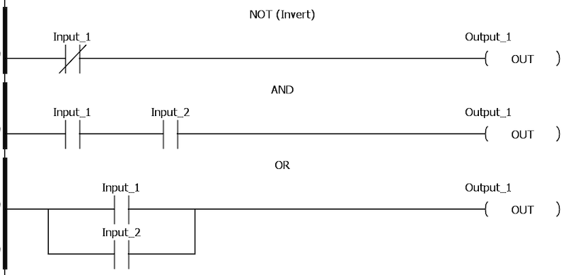
Figure 3. Ladder diagram showing an inverter boolean logic structure.
Boolean Logic Structures: NAND, NOR
The next two logical combinations are NAND as well as NOR. To best consider their effect in ladder logic, think of the AND/OR logic, respectively; the result is the exact opposite. Whatever combination made the original logic True is now the exact combination making the output false.
Regarding the NAND: “Output_1 will be True if either Input_1 or Input_2 are False”.
As an example, two liquid tanks must be full, each monitored by a sensor. If either sensor goals false, an alarm must sound. Now, this could be accomplished with N.C. real-world sensors, like an E-stop circuit, but it can also easily be accomplished with existing N.O. sensors using the NAND logic.
The NOR is more typical for an emergency stop (e-stop) situation (as shown in figure 4). “Both Input_1 and Input_2 must be false for Output_1 to remain True.”
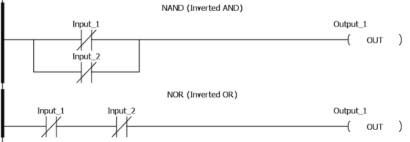
Figure 4. NAND versus NOR logic in a ladder diagram.
Finally, there are two combinations used more rarely in PLC logic, yet still exist in boolean logic.
Boolean Logic Structures: XOR, XNOR
Exclusive OR (XOR) means the output will only be True if Input_1 is True and Output_2 is False, or the reverse. It’s sort of like OR, except that OR also works if both are True.
Exclusive Inverted OR (XNOR) is True only if both inputs are False, or if both inputs are True. Again, it’s the opposite of XOR.
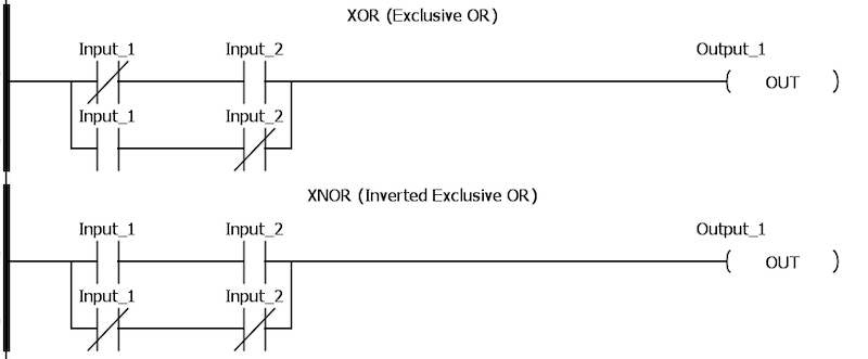
Figure 5. Ladder diagram example of XOR and XNOR logic.
PLC logic is, of course, not limited to these simple combinations.
Nearly every PLC code is designed using combinations of all of the above simple logical statements. However, every code is built with these as the foundation.
Another important piece to keep in mind is that the PLC, being a digital processor, is not limited in what real-world contacts it can handle. Although the symbol in the ladder may appear as an N.O. or N.C. contact, it certainly can be reversed in the real world. Flexible, but with an added layer of confusion.
Bitwise Logic
One other topic to cover briefly is the bitwise instructions. In this case, the inputs are integers, not bits, which seems counter-intuitive.
These instructions compare the bits in two integers, one bit at a time, to determine the overall solution integer. Consider two 16-bit integers that will be AND’ed together. First, the 2^0 (least sig) bits will be compared. If they are both True, the 2^0 bit in the output will be True. In this way, all 16 bits are compared, one at a time, and the 16 bits of output will be determined.
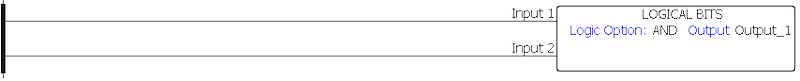
Figure 6. Example of a bitwise logic AND.
Since two integers are compared, bitwise operations may include AND, OR, NAND, NOR, XOR, and even XNOR.
Since a PLC is a computer, it operates by comparing conditions of discrete inputs to determine the state of discrete outputs. As long as we can summarize codes down to a basic, fundamental level, even the most complex ladder logic projects may be analyzed one line at a time.


Figure 2 needs an else clause.