Facebook
 Google
 GitHub
 Linkedin
Intro to Boolean Logic with FBD PLC Programming
Learn about some of the basic Boolean logic gates using the graphical PLC language of function blocks, recreating ladder logic and other IEC languages with a digital flair.
When you use words like “logic gate,” “multiplexer,” or “bitwise,” many electrical engineers will know exactly what you mean. The high and low digital logic levels energize TTL and CMOS gates to produce exact outputs, but, surprisingly, this same thing happens inside PLCs.
Set the Stage: A Simple FBD Program
For those engineers more familiar with the software version of logic (looking at the ladder and structured text folks), function block programming is just the visual representation of the integrated circuit gates that dominate electrical engineering. Those integrated circuits (ICs) have a purpose and name, and the various pins on the chips are interconnected with wires. This is the same method used for FBD programming, except the wires are just relational lines on the screen.

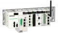
Figure 1. The Crouzet Millenium Slim PLC in a simple training bench setup.
For a brief introduction, we’ll start with a simple FBD program to connect the inputs of our PLC straight to the outputs. The hardware (shown above in Fig. 1) is a Crouzet Millenium Slim PLC programmed with Crouzet Soft. In Fig. 2, each input is designated with an icon to show the type of I/O device in the real world.

Figure 2. Simple input-to-output function block diagram program.
Basic Logic Gates: AND, OR, NOT
Three fundamental logic gates form the building blocks of all others, plus all the rest of the dedicated ICs. Technically, you could build any circuit from these three gates, but that would be exhausting. Fortunately, we have access to an entire library of more complex functions.
The AND gate means that all inputs must be active for the output to energize. There can be more than two inputs to an AND function. In the image below, we see how this looks first in a ladder format and then in an FBD format. It’s an extremely common logic arrangement.

Figure 3. AND logic using ladder, structured text, and function block formats.
OR logic is quite similar in form and popularity to AND logic. In this situation, any of the inputs (or any combination of inputs) must be active for the output to energize. The OR logic is presented below in LD and FBD formats.

Figure 4. OR logic using ladder, structured text, and function block formats.
The final basic gate is the inverter, or NOT gate. In typical PLC logic, we interpret this as “if the input is OFF instead of ON, then do this thing.” However, in FBD world, we only have one instance of the input, so we must invert that signal to achieve the same result. In the following example, Input 1 or 2 may energize the relay in Output 1, but only Input 2, when OFF, may energize the light. We would state this as “NOT In 2.”

Figure 5. In this example, In1 OR In2 equals Out1, whereas NOT In2 equals Out2.
Advanced Gates: NAND, NOR, and XOR
The next set of logic gates, NAND and NOR, are built by inverting the output of the AND and OR, respectively. However, this is a bit tricky to process mentally in a ladder logic or circuit setup.
Going back to the AND logic, we would explain it: "All of the inputs being energized is the only way to turn the output on.” NAND is the inverted output of an AND gate, meaning that all of the energized inputs would be the only combination that turns the output OFF.
Fair enough, but when we design the ladder logic, we might intuitively design an AND series of normally closed inputs; after all, NAND is simply the inverse of AND, so we just design it with the opposite kind of input, right? The problem is that the output is the inverted part, not the inputs. The logic will not be correct; instead, it will act like... Well, you’ll see in a minute.
Instead, the correct way to design NAND logic is to place normally closed inputs in parallel. That way, you must energize (open) all of the inputs before the path to the output is blocked, and it turns off. You can easily make NAND gates with more than two inputs.

Figure 6. NAND ladder logic and FBD command.
Along the same lines, we cannot build NOR logic by placing N.C. (inverted) inputs in parallel (OR). As we have seen, this forms NAND logic.
To explain NOR logic, we might state that “the only way to turn on the output is if ALL of the inputs are de-energized.”
This logic is the way e-stop circuits are designed. We only want to energize the e-stop circuit when ALL the e-stop buttons are unpressed. Press any button, no matter which one, and the entire circuit chain should break. This sounds like a series circuit built with any number of standard NC contacts.
This is exactly how to build NOR logic: placing normally closed contacts in series, as shown below.
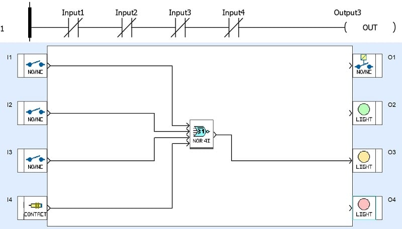
Figure 7. NOR logic.
The last logic gate in typical PLC logic is an odd one called the XOR gate. This stands for “exclusive OR, " meaning it acts a bit like a normal OR gate, but if both inputs are energized, the output turns off again. In plain English, it would sound like “the output will turn on if, and only if, one OR the other input is energized, but not both.”
This XOR gate is unique in that it only allows two inputs. Because of the logic, we run into a challenge trying to explain it any more. Would it mean that it only turns on if exactly one of the inputs is energized? Or, does it mean that it turns on in every condition except when all inputs are on or off? To avoid this ambiguity, this gate only has two inputs.

Figure 8. XOR logic.
Advanced Gates: What’s Next?
So far, we have seen some great, simple examples of digital logic implemented with FBD and ladder diagrams. But what happens when you need custom logic or things like selector switches for inputs or trigger and pulsing outputs? In the next article, we’ll look at these advanced digital logic functions using a function block template.