Facebook
 Google
 GitHub
 Linkedin
PLC Ladder Logic on an Arduino: Introduction to OpenPLC
Build a low-cost PLC using the Arduino Uno and the open-source industrial controls software, OpenPLC, to learn how to program with ladder logic, beginning with your first OpenPLC project: Hello World.
OpenPLC is an open-source industrial controls platform that allows the transformation of popular microcontrollers into a programmable logic controller (PLC). OpenPLC is a fully functional open-source PLC based on the International Electrotechnical Commission’s (IEC) standard 61131-3 on Functional Programming Languages.
There are five functional programming languages associated with IEC 61131-3 standard; they are Ladder Diagram (LD), Structured Text (ST), Instruction List (IL), Sequence Function Chart (SFC), and the Functional Block Diagram (FBD). The most common programming language used with the PLC is LD. The IEC 61131-3 standard considers software and hardware requirements to develop effective, low-cost automation control systems.
Versions of OpenPLC
The technical development path of the OpenPLC platform consisted of two basic versions of the open-source programming language toolchain, version 1.0 and version 1.2b. Version 1.0 provides a simulator for testing LD programs. The software version can run ST code on a target Microchip ATMEGA328 8bit microcontroller. Version 1.0 provides a runtime feature that allows installing C-code and displaying the Microchip-based PLC input/output devices running on the ATMEGA328 microcontroller. Figure 1 shows a typical runtime dashboard executing a Hello World LD program.
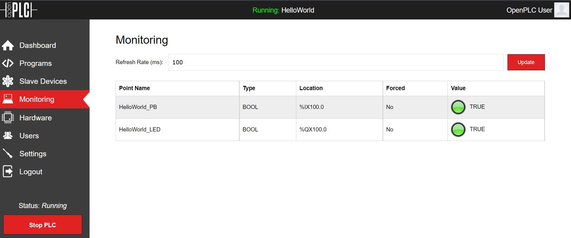
Figure 1. OpenPLC Hello World runtime dashboard.
Version 1.2b provides a simulator for testing LD programs but can program additional Arduino platforms and popular microcontrollers like the ESP32 and the ESP8266 programmable devices. Figure 2 illustrates the Hello World simulator LD program environment.
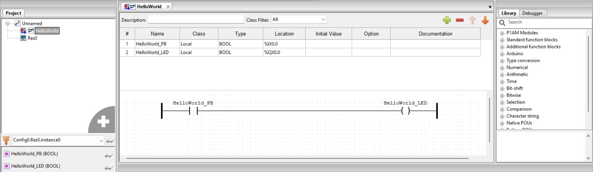
Figure 2. The Hello World simulator LD program environment.
Using OpenPLC with an Arduino Uno
With an understanding of the OpenPLC open-source platform, you are now ready to build an Arduino Uno or compatible PLC. The first step to building an open-source PLC is downloading the development tool from the website here.
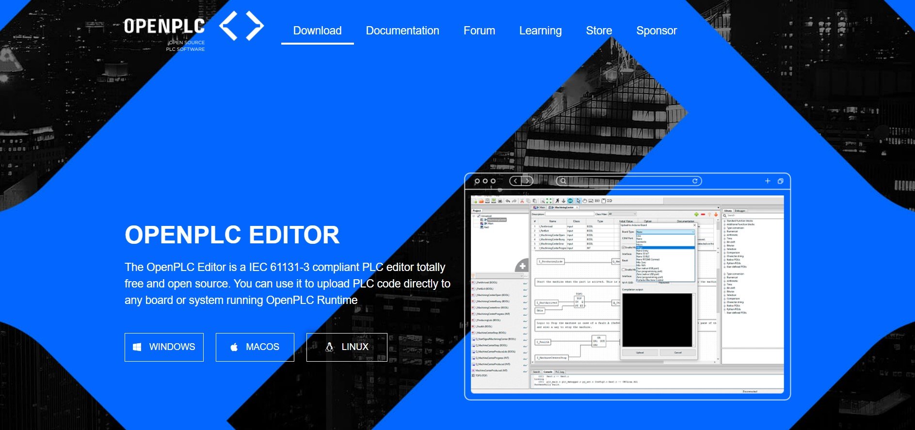
Figure 3. OpenPLC website.
Select the software for your PLC development machine’s operating systems. With the OpenPLC software downloaded from the website, double-click to run the installer.
Congratulations on installing OpenPLC!
You are ready to build your first OpenPLC project, Hello World.
First OpenPLC Project: Hello World
This project uses an Arduino Uno or compatible board along with a few discrete electronic components on a solderless breadboard. The Hello World PLC project lights up an LED when pressing a tactile pushbutton switch. You will wire your Uno compatible PLC using the electronic circuit schematic diagram shown in Figure 4.
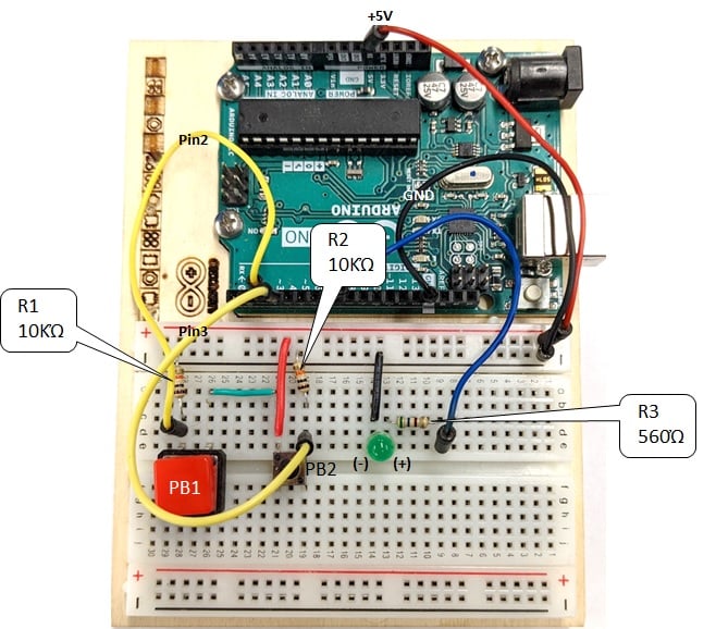
Figure 4. The Arduino Uno PLC electronic circuit schematic diagram.
As an additional reference, here is the author’s solderless breadboard PLC shown in Figure 5.
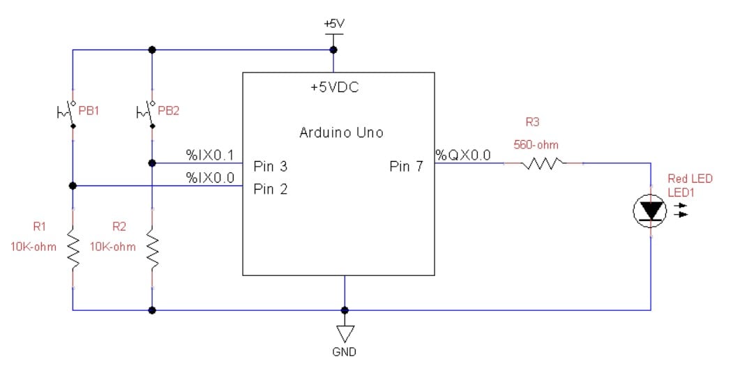
Figure 5. The author’s actual prototype Arduino Uno PLC wiring diagram.
The tactile pushbutton switch PB1 and PB2 are wired as digital logic switches. When pressing PB1 or PB2, approximately +5 VDC is applied to pins 3 and 2, respectively. To illustrate the method of testing the wired digital switches, Figure 6 is presented. You will notice in the Tinkercad circuit model the digital voltmeter is attached across resistor R1. The USB cable links the Arduino PLC to the programming computer. A power-on LED will be visible on the Arduino Uno printed circuit board (PCB); this indicator signifies the microcontroller and the supporting electronic circuits on the printed circuit board (PCB) are powered on.
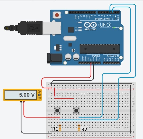
Figure 6. Testing a digital logic switch.
Place your digital voltmeter across R1 of the actual PLC prototype shown in Figure 5 and press the PB1 tactile switch. An approximate reading of +5 V should be displayed on the electrical measurement instrument’s LCD. If the voltage reading is not approximately +5 V, check your wiring and repeat the measurement. Perform the same test measurement on the PB2 tactile switch. Press PB2 to read approximately +5 V on the digital voltmeter.
Congratulations, you have two functional digital logic switches for your Arduino PLC.
The next step is to wire and test the output LED indicator on a solderless breadboard. Figure 7 shows the Tinkercad circuits model of the wired and powered output LED indicator on the solderless breadboard. Use this circuit model as a reference when testing the output LED indicator on the actual solderless breadboard prototype.
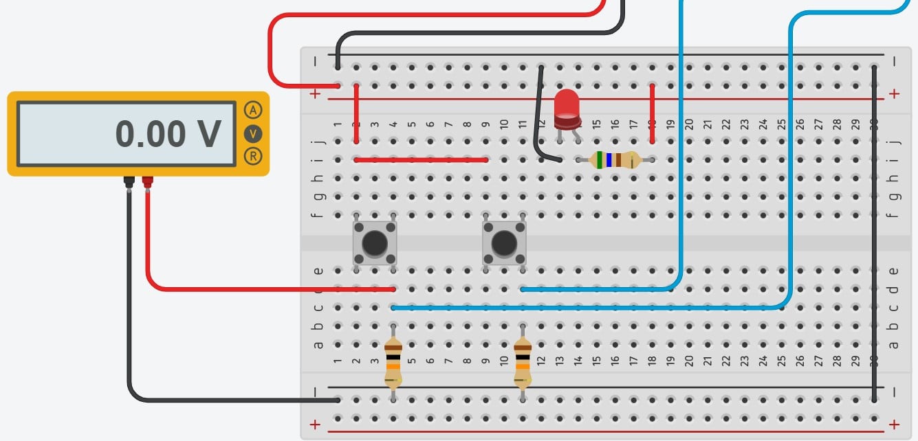
Figure 7. A functional output LED indicator.
If your output LED indicator is turned on, job well done! Your output LED indicator is working properly.
Remove the USB cable from your PLC development machine’s USB port. Replace the red wire attached to the 560 Ω resistor with a long jumper wire. You will take the end of the jumper wire attached to the 560 Ω resistor and insert it into digital pin 7 (D7) of the female header connector mounted to the Arduino Uno.
You have wired and tested digital logic switches and an output LED indicator of your prototype Arduino Uno PLC.
The final stage of the PLC project is to build and upload the OpenPLC Hello World LD program to the Arduino Uno PLC. Before proceeding to the final step of the OpenPLC project, insert the USB cable into your PLC development machine’s USB port.
Building a Basic Ladder Diagram Program
Next, right-click on the computer create a project folder (recommended in My Documents or another simple location) in which the OpenPLC-generated files are stored with the LD program. You can name the project folder ‘HelloWorld’.
With the project folder created, open the OpenPLC software and select the HelloWorld project folder, and the OpenPLC editor will appear on the screen.
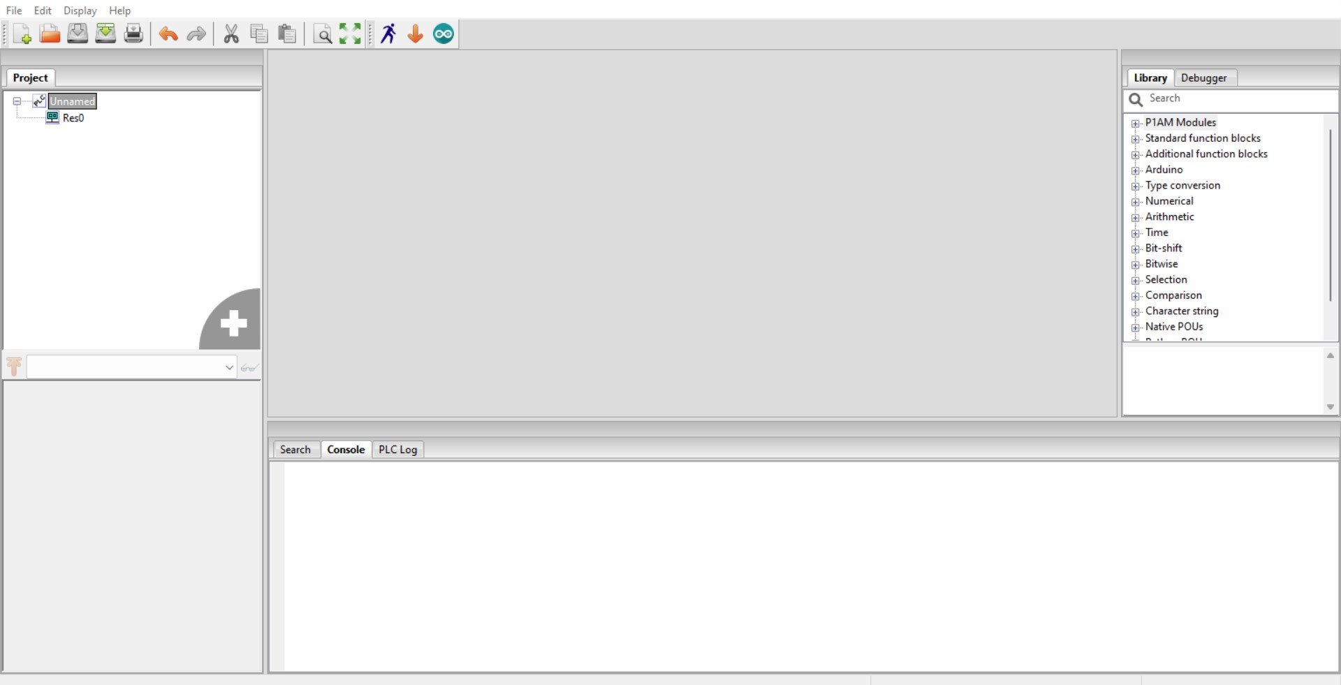
Figure 8. The OpenPLC editor.
Create the HelloWorld LD program by selecting File>New.
A small dialog box will appear on the screen. Fill in the textbox labeled POU Name with HelloWorld as shown in Figure 9. For the Language dropdown list, select LD (for Ladder Diagram). Click the OK button to finalize creating a new LD program.
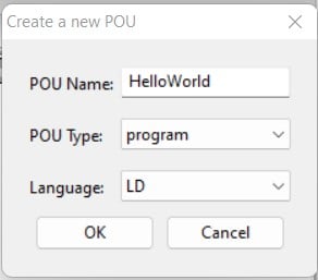
Figure 9. Completing the project box information.
With the project box completed, you are ready to create I/O tags. For the Hello World LD, there are two tags: HelloWorld_PB and HelloWorld_LED. Click the plus sign to create the two I/O tags. Your I/O tags listing should look like Figure 10.
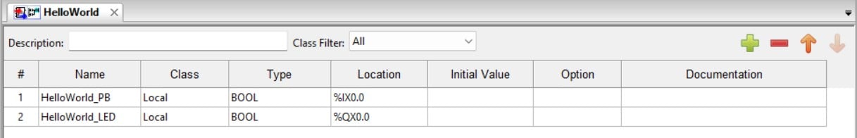
Figure 10. HelloWorld I/O tags listing.
You will notice the columns’ Type and Location in the I/O tags listing. Click in the HelloWorld_PB’s Type (data type) cell and select BOOL. Repeat the selection process for the HelloWorld_LED. With the tactile pushbutton switch providing digital information (ON/OFF) and the output LED indicator being commanded to turn ON and OFF, the data type is Boolean, thus the selection of BOOL. The location column is the PLC address for the specified I/O pins of the Arduino Uno. Type the addresses as shown in Figure 10.
With the I/O tags listing completed, you can now create an LD program. The two primary PLC bit instructions you will use for the Hello World project are the Examine If Closed (XIC) and Output Energized (OTE) The location of these bit instructions is in the programming toolbar.
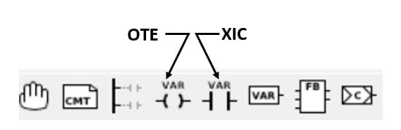
Figure 11. PLC Bit instructions.
Select the XIC and OTE bit instructions and place them respectively on the left and right sides of the LD program build section of the OpenPLC editor. The tags you created will be associated by selecting the correct bit instructions. Figure 12 shows the tags associated with the correct bit instructions.
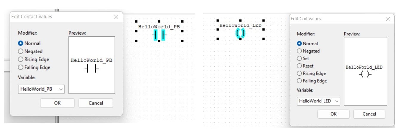
Figure 12. Placing and configuring the XIC and OTE bit instructions.
Select the power rail and configure the number of pins to connect the XIC and OTE bit instructions and build the single rung of logic. The pins are the rungs for the LD program. Figure 13 illustrates the selection and configuration process of the power rails.
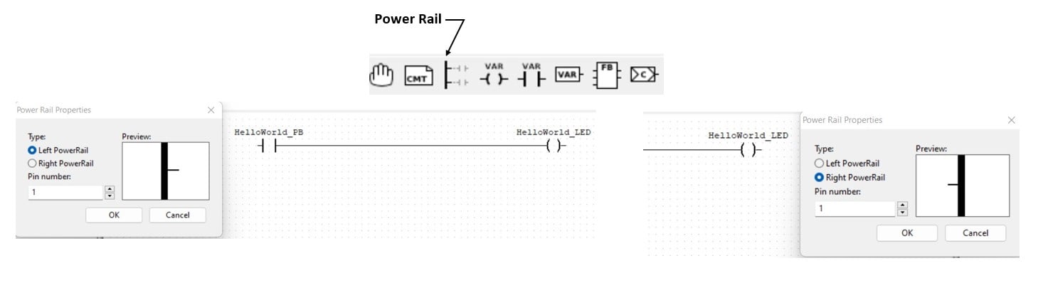
Figure 13. Selection and configuration of the power rails.
The final step of building the LD program is connecting the XIC and OTE bit instructions together. Select the right end of the HelloWorld_PB XIC bit and drag it to create a line. Continue dragging the line to connect to the left side of the HelloWorld_LED OTE bit. This line creates a rung to manage the XIC and OTE bit instructions control logic operation. The completed LD program is shown in Figure 14.
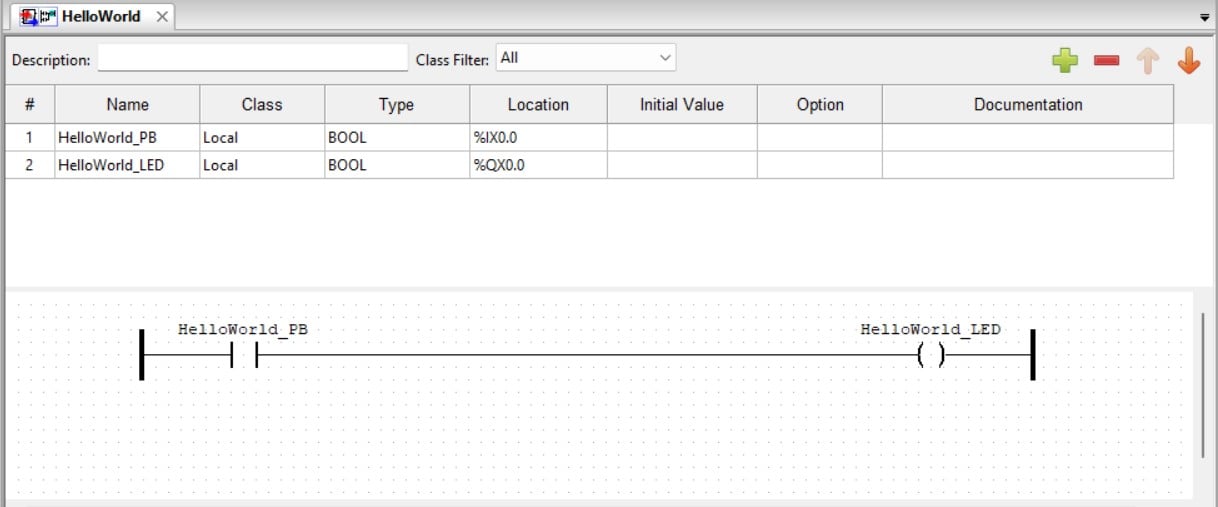
Figure 14. The Hello World LD program.
Super job building the Hello World LD program!
To run a simulation on the LD program, click the sunglasses next to the Config0.Res.instance0 dropdown box. You should see the left rung attached to the HelloWorld_PB XIC bit instruction turn green, indicating the LD program is ready to be simulated, as shown in Figure 16. Select the running man at the taskbar to run the LD program. The ‘PLC Started’ text will be displayed in the PLC log section of the editor.
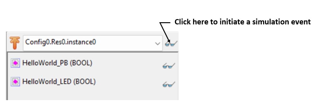
Figure 15. Starting an LD simulation event.
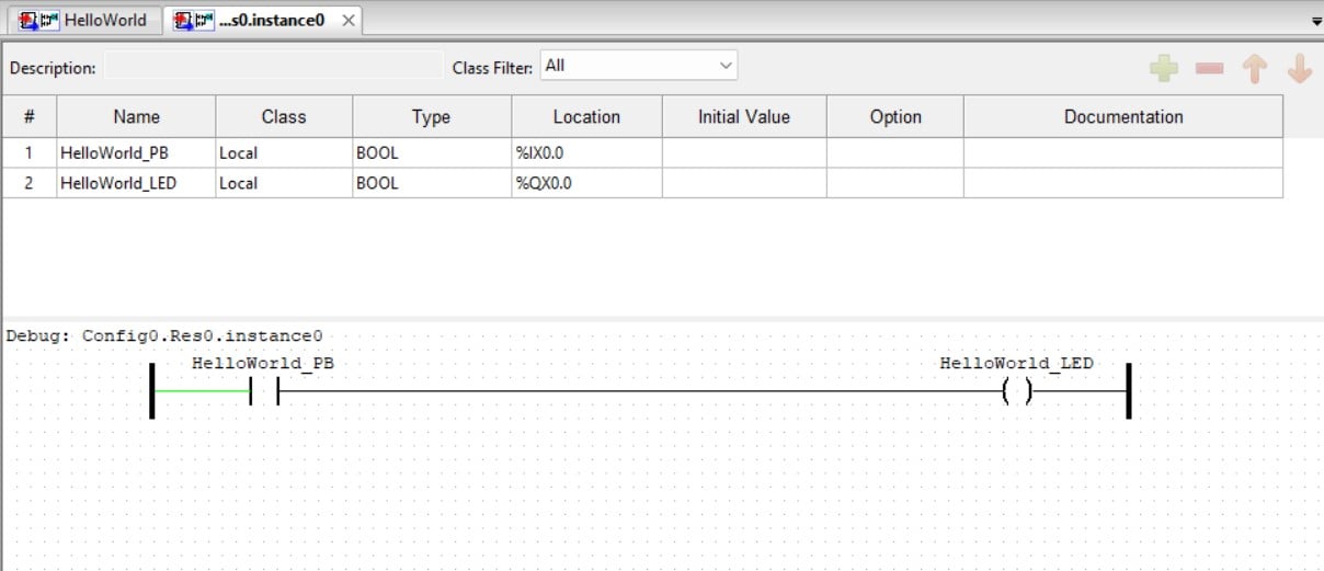
Figure 16. Hello World LD is ready for simulation.
To interact with the simulation, right-click to select ‘Force True’ from the presented selection list. The Hello World_LED OTE bit should turn green. Right-click again to toggle the force false. You will notice the Hello World_LED OTE turning OFF or displayed as black.
Congratulations, you have run a simulation event for the Hello World LD program. The final step of the project is to upload the LD program to the actual Arduino PLC.
Uploading and Testing the Hello World Ladder Diagram Program on the Arduino Uno PLC
Click the stop sign to turn off the simulation event. Reset the LD program by clicking a small box next to the HelloWorld LD program name located on the left side of the editor.
To upload, click the Arduino Uno icon in the taskbar to select the correct USB communication (COM) port and the appropriate microcontroller development platform. Figure 17 shows the configuration panel for the selected COM port and the Arduino board.
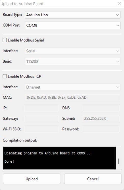
Figure 17. Configuration panel.
You may need to identify the correct COM port using your PLC development machine’s Device Manager. With the Arduino Uno board and the COM port selected, click the Upload button. After the runtime tool has converted the ST program to C-code then to a binary file and uploaded it to the Arduino, a ‘done’ message will be displayed in the compilation output window, visible at the bottom of Figure 17. Press the PB1 tactile switch on the solderless breadboard prototype, and the LED shall turn on. Releasing the tactile pushbutton switch will turn off the LED.
You have now built a low-cost PLC using an Arduino and the OpenPLC software!
In the next article installment, the PB1 tactile switch will be replaced with an Industrial Start/Stop pushbutton station. You will learn how to program your OpenPLC-based Arduino to perform a Start/Stop Control circuit.
Interactive Quiz: Inverted Hello World
-
Modify the LD program shown in Figure 16, where the HelloWorld_LED indicator turns on immediately.
-
Pressing the tactile pushbutton switch will turn off the LED indicator.
The solution to the Interactive Quiz will be presented in the next OpenPLC article!
Want to test your knowledge of PLCs? You think you N.O. a lot about ladder logic? Are you a normally-open or normally-closed minded engineer?
Check out our PLC Programming worksheet!