Facebook
 Google
 GitHub
 Linkedin
PLC Ladder Logic on an Arduino: Building a Start-Stop Circuit
Learn how to prototype an industrialized OpenPLC Arduino PLC control station concept. This hands-on project will illustrate converting a relay ladder control circuit into a Ladder Diagram (LD) program.
Check out the previous Arduino OpenPLC article, including installation and setup instructions:
PLC Ladder Logic on an Arduino: Introduction to OpenPLC
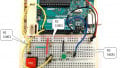
In our previous article, we provided an introduction to OpenPLC as a hands-on project, converting an Arduino Uno into an entry-level PLC. This illustrated the ease of building a low-cost functional automation controller with the popular microchip ATMEGA328 microcontroller-based electronics prototyping platform. In this article, we will provide information on wiring and testing a control station for the OpenPLC Arduino platform to construct a start-stop control circuit.
The Start-Stop Control Circuit
In industrial controls, there is a fundamental approach to allowing operators to engage with automation machine systems: the start-stop control circuit. The start-stop control circuit allows a hands-free approach to starting an automated machine or process by pressing a pushbutton switch. The pushbutton switch is only a momentary operation where the operator releases the switch after pressing it.
To accomplish a process control function, a latching feature is required. The latching feature consists of having an electromechanical control relay (CR)’s contact wired in parallel with the start pushbutton switch. The CR coil is energized by the current flowing through closed contacts of the series-wired start and stop pushbutton switches.
The parallel wired CR’s NO contact will provide an electrical current that will maintains a sealed pathway around the start pushbutton switch once it is released and returned to open. The CR’s second NO contact wire on the second rung of the control circuit will close, thus turning on the electrical load, here a pilot lamp (PL), is wired to it. To turn off the PL electrical load, press the stop pushbutton switch. Figure 1 illustrates this start-stop relay ladder control circuit.
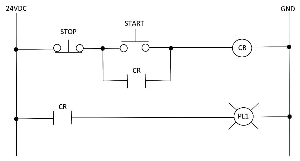
Figure 1. Start-stop control relay ladder circuit.
The Control Station Concept
The start-stop control station circuit shown in Figure 1 will aid in the development of an OpenPLC automation concept. The developmental aspect of the design concept is to wire an industrial up-down switch box to the Arduino PLC. The switch box will perform the pushbutton switch operation as shown in Figure 1. A press and release of the ‘up’ switch will operate as the start switch, thus allowing the Arduino’s digital pin 7 to turn on an LED. Pressing the ‘down’ switch will turn off the LED. The control station concept block diagram is shown in Figure 2. The electrical behavior of the control station pushbutton switches will be managed using an OpenPLC ladder diagram (LD) program.

Figure 2. The control station concept represented as a block diagram
Wiring and Testing the Control Station Pushbutton Switches
The control station pushbutton switches provide the control signals to the Arduino to operate the LED. It is important to have the control station switches wired properly to ensure the start-stop LD program works correctly. Therefore, attaching the wires to the correct terminal block points of the switch box will achieve correct control operation. The electrical symbol for the switch box is provided in Figure 3.

Figure 3. The up-down control station switch box electrical symbol
This project can also be accomplished by using two normally open pushbuttons, etiher tactile breadboard or industrial size. For this tutorial, the metal enclosed switch box will be demonstrated.
The wiring to the switch box is quite easy to accomplish.
By removing the top and bottom fasteners, the switch box cover is removed. Push the top metal knockout of the box so that three electrical wires may pass through it. Be sure to sand the metal knockout edges to prevent cutting the insulation from the wires.
With the removal of the cover, the terminal block for attaching electrical wires can be achieved. Dupont or 26 AWG solid wire is attached to the three terminal screws. The shorting bar provides a common point for switching either high side voltage or ground. For the Arduino PLC, +5 VDC will be wired to the shorting bar, thus switching high-side control voltage signals to digital pins 2 and 3. Figures 4 and 5 show the cover removed and electrical wires attached to the control station switch box.
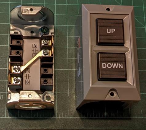
Figure 4. Switch box cover removed

Figure 5. Attachment of electrical wires to the control station switch box
After replacing the cover on the switch box, take an ohmmeter and perform an audible continuity test of the electrical wiring attached to the up and down pushbutton switches. Attach the ohmmeter between the common (COM) wire and either of the other electrical wires. Press and hold one switch to hear an audible continuity tone. If the tone is heard, proceed to test the other wire and switch. Figure 6 illustrates testing the control station switch box electrical wiring with an ohmmeter set in audible continuity mode.

Figure 6. Performing a continuity test of the attached wires to the pushbutton switches
Congratulations, you have a functional control station switch box to wired to your Arduino PLC! Add labels to the three attached electrical wires for identifying the two switches and the COM. Secure the cover with two removed fasteners. The next step of the OpenPLC project is wiring the switch box to the Arduino.
Wiring the Switch Box to the Arduino PLC
The next in the project is to wire the control station switch box to the Arduino. The COM wire will be wired to the +5 VDC rail of the solderless breadboard. This breadboard will also be used to contain the two tactile switches that will operate the program if you do not have an enclosed switch box.
The ‘up’ electrical wire from the switch box will be inserted into the breadboard cavity where digital pin 2 of the Arduino is wired to the 10 Kilohm (KΩ) pulldown resistor. The ‘down’ electrical wire will be inserted into the solderless breadboard cavity where digital pin 3 of the Arduino is wired to the other 10 KΩ pulldown resistor. Figure 7 provides the electronic circuit schematic for wiring the control station switch box to the Arduino PLC.
If you do not have an enclosed switch box:
Simply omit the COM, ‘DOWN_STOP’ and ‘UP_START’ wires from the diagram in Figure 7, allowing PB1 and PB2 to operate the system alone.

Figure 7. Control station switch box to Arduino PLC electronic circuit schematic diagram.
With the switch box wired to the Arduino PLC, an electrical test can be performed.
Place a digital voltmeter across the R1 10 KΩ pulldown resistor. Power the Arduino by attaching a 9 V battery to the barrel connector (A USB or AC power supply will work as well). The green ‘ON’ LED will be active. Press and hold the ‘up’ switch to read approximately +5 VDC. Attach the digital voltmeter across resistor R2 and perform the same voltage measurement test using the ‘down’ switch. If a reading of approximately +5 VDC was not measured, ensure the digital voltmeter is electrically connected across the pulldown resistors. Repeat the test to ensure correct control voltage signals are being applied to digital pins 2 and 3 of the Arduino. The next part of the OpenPLC project is to build the LD program.
The Start-Stop Ladder Diagram Program
The start-stop LD program is created by referring to the relay ladder circuit presented in Figure 1. Following the OpenPLC setup instructions provided in the PLC Ladder Logic on an Arduino article, create the tag listing table using Figure 8. The documentation column provides a short description of the bit instruction used in the start-stop LD program.

Figure 8. The start-stop tag listing table.
Using the tag listing table, the start-stop LD program can be built using Figure 9. To ensure the LD program will work properly, note the negated bit instruction used with the DOWN_Stop tag.

Figure 9. The completed start-stop LD program
Attach the Arduino to your computer USB port. Upload the LD program to the Arduino PLC to test the final automation control operation. Using a mouse, click the Arduino logo on the OpenPLC taskbar. Select the correct USB port to upload the LD program. Once the LD program has been uploaded, press and release the ‘up’ switch—the LED will turn on. A press and release of the ‘down’ switch will turn off the LED. Figure 10 illustrates the complete OpenPLC start-stop control circuit.

Figure 10. The OpenPLC start-stop control circuit.
The following video clip will illustrate the final operation of this OpenPLC project build. The next OpenPLC project installment will explore using an all-inclusive project kit with pre-mounted electronic components to a PCB assembly to construct a transistor relay DC motor controller. The project kit will allow rapid development and enhancement of OpenPLC LD programs for the Arduino PLC!
Interactive Quiz: Hello World LD Program Solution

Interactive Quiz: Logic OR
Using the control station switch box, create a logic OR gate function. Upon pressing either switch, the LED will turn on. The solution will be provided in the next OpenPLC project article!