 Facebook
 Google
 GitHub
 Linkedin
Info Byte: What’s the Reason Behind Relay Terminal Numbering?
Any industrial electrician can instantly recognize a relay, but when it comes to wiring, why are the terminals numbered in such apparently random order?
Wiring relays can be a difficult challenge even for experienced electricians. Determining the screw terminal locations of common, N.O, and N.C. terminals, as well as the coil, is difficult to begin with. Add in the various sizes, single- vs double-pole configurations, and the best you can hope is that a drop-in replacement is readily available on the supply shelf.
In this Info Byte, learn the purpose and reason behind the often-confusing terminal numbers. You might still have to look up those wiring diagrams, but perhaps we can remove some of that aggravation that stems from confusion.
Check out our exclusive ebook: The Complete Guide to Relays!
Two Main Standards
Industrial control relays are primarily produced under NEMA and IEC standards, which means that you might see relays with one or the other, but often both number conventions side-by-side.
NEMA Relay Wiring Numbers
NEMA Ice Cube
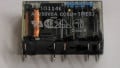
Under the NEMA (National Electrical Manufacturers Association) standard, the terminal numbers are labeled 1-14 in the largest typical 4PDT relays. Since you are more likely to encounter a smaller one, the numbers for a smaller DPDT relay might look like this:
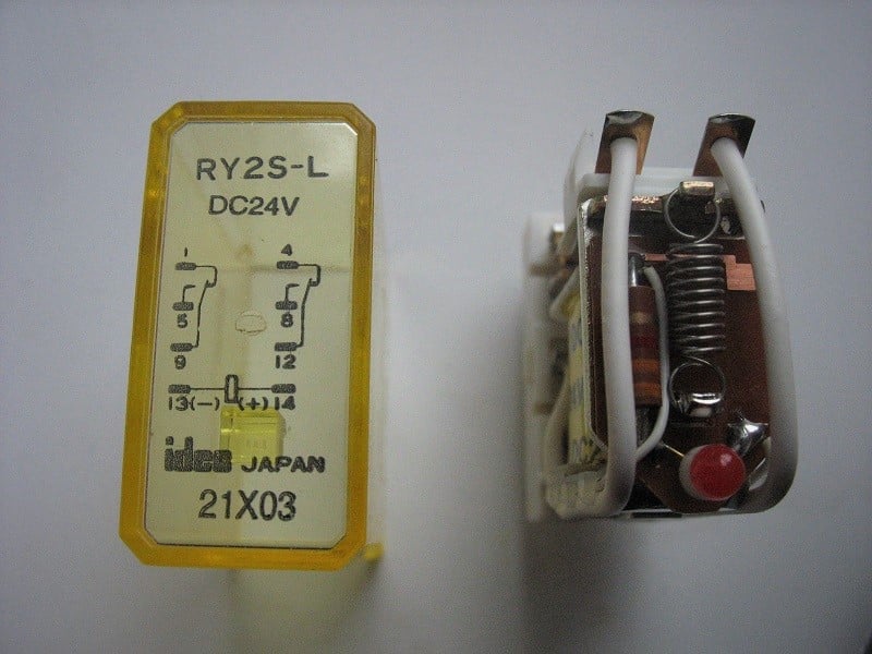
Figure 1. A DPDT relay showing the NEMA numbers.
1-5-9 for the first contact set, and 4-8-12 for the second contact set, then 13-14 for the coil.
Comparing these to the larger common double-pole relay, the 4PDT, we would also find all of the mysterious missing numbers in between those on the double-pole model.
For this relay with four contact sets, 1-4 indicate the normally closed (N.C.) terminals. 5-8 indicate the normally open (N.O.) terminals. Finally, 9-12 are the common leg terminals to supply voltage on a dry contact.
Terminals 13 and 14 indicate the coil in the NEMA convention.
As an example, suppose you needed to connect a circuit to an N.O. set of contacts. You should expect to use terminals 5 and 9, or alternatively, 8 and 12.
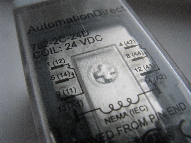
Figure 2. A DPDT relay with dual NEMA and IEC numbers.
For an N.C. connection, the choice would be 1 and 9, or perhaps 4 and 12.
Regarding the smallest relays, we should expect an SPDT relay to have only terminals listed 1 - 5 - 9 - 13 - 14. From the preceding description, it is now clear to see what each number represents.
NEMA Octal Base
A slight variation occurs in the NEMA convention for the circular keyed base with 8 pins. For these relays, the numbers 1-8 orbit the base. Pins 2-7 connect to the coil, with 1, 3, and 4 being the first set of contacts (common, N.O., and N.C. in that order) and the second set being 8, 6, and 5 (common, N.O., and N.C. in that order).
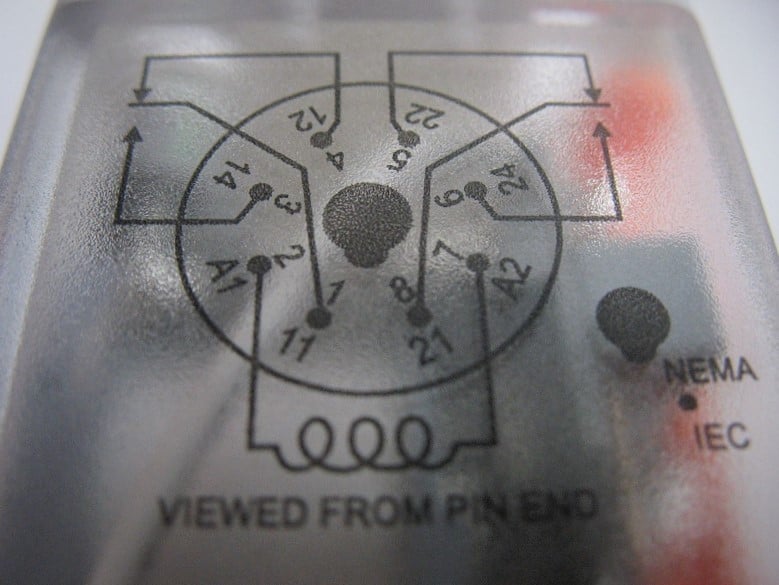
Figure 3. An octal relay with dual NEMA and IEC numbers.
IEC Relay Wiring Numbers
The International Electrotechnical Commission (IEC) numbers can be used in a wider variety of ways without losing meaning.
Terminals are always 2-digit numbers, and both digits should be interpreted separately.
The first digit identifies the set of contacts (or ‘poles’), starting with 1, but these relays can be more than just 4 poles.
The second digit identifies the purpose of the terminal:
1 = common for the N.C. contact
2 = the N.C. contact
3 = common for the N.O. contact
4 = the N.O. contact
IEC Double Throw (xPDT) Relays
If the relay is a double-throw, where the common terminal connects to both sets of contacts, simply omit #3 from the list of functions - there's only one common.
Therefore, for the first contact set, the common would read 11 (or as I would say, “one one”), the N.C would read 12 (or “one two”), and the N.O. would read 14 (“one four”, okay, I’ll stop now).
If there was a second contact set, the ordered numbers would be 21, 22, and 24. For the large 4PDT model, the numbers would end with the final set being 41, 42, and 44.
The coil terminals are unique, as they are designated A1 and A2 - not often a cause for confusion.
IEC Single Throw (xPST) Relays
Many single throw relays have more than 4 poles, but each pole is limited to only either N.O. or N.C.
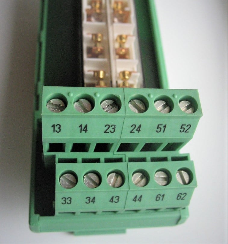
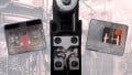
Figure 4. A 6PST relay with integrated terminal blocks, each set appropriately showing IEC numbers for N.O. or N.C. contacts.
In the case of this 6PST relay shown below, the first number clearly indicates the contact set - 1 through 6.
The top left terminals are 13 and 14, and if we look at the breakdown of the terminals in the previous section, 3 and 4 indicate an N.O. set. Therefore, contact set 1 is an N.O. set.
This appears to be the case as well for contact sets 2, 3, and 4.
However, contact sets 5 and 6 consist of 51 and 52, as well as 61 and 62. Referencing the previous breakdown again, these would appear to be N.C. sets.
A closer look at the picture will indeed verify 4 sets of N.O. contacts, and 2 sets of N.C. contacts.
Contactors
As a final end note - contactors’ auxiliary terminals are controlled by these same IEC guidelines. Check it out (carefully) the next time you look inside a cabinet, and you can easily identify whether the set is N.O. or N.C. by the numbering, although it’s usually printed as well.
It's true, wiring relays is frustrating... It may always be frustrating. But at least it doesn’t have to be quite as confusing as it was before!
Love relays? So do we! Check out our whole collection of relay content:
- Differences Between Electromechanical and Solid State Relays
- How to Troubleshoot Mechanical Relays
- Info Byte: Preventing Relay Burnout with Flyback Diodes
- Understanding the Differences Between Protection Relays vs Control Relays
- Info Byte: The Mystery of Ice Cube Relays–Coil Polarity
- I/O Module Debate: Digital Output or Relay Output?
- Contactors versus Relays - Differences and Applications
Do you have any helpful ways to remember relay wiring, or any best practices you keep in mind for a successful wiring experience every time?


I’d wondered why there were two sets of numbers on relay contacts. Super informative article! This will save me having to always look for relay schematics.