Facebook
 Google
 GitHub
 Linkedin
Wet vs. Dry Contacts: Knowing the Difference
Wiring design systems can become confusing when some switching devices send power to the load automatically while others do not. Often called ‘wet’ and ‘dry’ contacts, these devices are fairly easy to troubleshoot once the differences are understood.
In the world of control devices, we can find a nearly endless variety of brands, models, and functions of input devices. These take the form of switches, sensors, or relays, but no matter the environmental operation, we can boil them down to one simple purpose: to turn on and off at the proper moment.
When any sort of input device is energized, a circuit is completed inside. The job of the electrical engineer or technician is to determine how this device should work in order to drive the load. Once this is understood, troubleshooting can go beyond just blindly tracing wires on a diagram. When it comes to these input devices, there are two varieties of contacting methods, which are often referred to as ‘wet’ and ‘dry’ contacts.
With wet contacts, we expect the output terminal to be energized the instant the contact closes, and the voltage will be equal to the voltage of the device's power supply (industrial sensors, for example).
A dry contact, when energized, will not measure any output voltage unless a separate terminal is supplied with power, isolated from the device's own supply (industrial relay contacts are a common example).
But why are there two varying standards; is one better than the other? And why is it important to understand the difference?
Wet vs. Dry Contacts
The first point of note in this discussion: the terminology defined here only applies to discrete devices that are limited to on/off. Analog, or varying output devices, output a voltage or a current depending on the model, and the output is never a set of contacts. Therefore, the discussion of wet and dry contacts never applies to analog devices.
When we apply electricity to drive a sensor or relay, we expect an output circuit to be switched, perhaps by placing an object in front of the sensor (perhaps an optical transistor) or pressing a switch (to energize the coil of a relay). The internal contacts switch between their open and closed position, completing the circuit to drive the load.
Dry Contacts, Also Called Voltage-Free, or Potential-Free
In the dry contact switch method, an engineer must externally provide the source of electricity to be sent to the load, usually through a ‘common’ wire. This is the terminology used in a relay where we see the contact wires labeled common, normally open, and normally closed. It is also the most common type of output module on a PLC, where an IN or COM must be provided for every output terminal or group of output terminals.

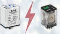
Figure 1. The RIB02BDC relay has dry contacts and can be used in a variety of power applications. Image courtesy of Industrial Controls.
Wet Contacts
Wet contacts are most likely to be seen in solid-state switching, such as sensors. Once power is provided, the simple switching action sends this same supply power off to the load device. No extra common power wires are required.

Figure 2. This proximity sensor utilizes wet contacts. Image courtesy of Grainger.
Simply summarized, dry contacts open and close a separate isolated circuit, and the output power is completely removed from the input power. Meanwhile, for wet contacts, the output power is immediately supplied along with the input and is only sent to the output terminal when the switching action has occurred.
Common Examples of Each Contact
There are two main benefits to be seen from each type of contact, and therefore the devices which use each method capitalize on these benefits.
All relays, including solid-state relays, use dry contacts. One of the advantages of using a relay at all is it provides the ability to get a different output voltage from that which was used to energize it. For example, a relay may have a 24V coil, but the contacts may allow nearly any voltage level for the load. This cannot be achieved with wet contacts, where the voltage output could only be the same as the coil.
Similarly, isolation is a major reason for using dry contacts. In most cases, these actually do output the same voltage as the input, so they may switch on and off with 24V and supply 24V to the output. But for reasons of control circuit protection, it is essential that the input and output circuits are removed and capable of withstanding hundreds or thousands of surge volts. For this reason, optoisolators and isolation relays must be dry contacts.
Sometimes, however, the simplicity of wiring takes priority over isolation. For small-signal control circuits, such as sensors, providing information to PLCs, all voltage levels are the same, and the power consumption of the sensor and the load together is very minimal. So it is very common to see the same wire providing power both to the sensor circuitry as well as being sent to the load wire, ready to transmit to the PLC when the switch is energized.
Finally, some switches are intended only to provide or remove power to downstream circuits, much like a circuit breaker. The same input wires which power the internal circuits also power the output terminals. This is exactly the internal construction of a ground fault interrupter (GFI) circuit.
Identifying Contact Types
Probably the easiest place to start with identifying which type of contact is used is to count the wires going to the device. If there are only three wires, it must be a wet contact. The internal circuitry must have a supply + and - (or line and neutral for AC), so if there is only one wire remaining, then it must supply that same power to the load.
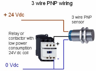
Figure 3. A PNP sensor has three wires and is a 'wet' contact device. Image courtesy of Schneider Electric.
Four wires would be counted on most control relays. Two of the wires must be used to power the device, just in a sensor. But in this case, the remaining two wires are for the + and - of the load circuit, completely isolated and often at a different voltage.
PLC modules are always dry contacts, regardless of whether they are relay or digital output types. Just because a PLC module says 24V, don’t expect it to supply that voltage simply by activating the output terminal. The output points are driven by the 5V logic from the processor, the power for the loads always comes from an external source. If relay, they can accept a variety of voltages. If digital, they are often restricted to one specific voltage. But no matter the type, this voltage must be supplied through a common or input terminal.

Figure 4. This relay shows an example of isolated dry contacts: the copper coil terminals are on the left and all the contact terminals are on the right.
Be careful — just because a device has four wires doesn’t always mean dry contacts. In rare cases, a sensor can drive two different loads, or have a normally open and closed terminal, but this is rare since they are usually not used at the same time.
If a control device with some sort of switching action has terminals for only two wires, this most likely indicates that it is a dry contact, and the switching action is performed within the body of the larger device. Most variable frequency drives contain a programmable relay output to be switched when a certain action occurs. The relay terminals will make use of a COM and either a normally open or normally closed contact, two wires.
A Review of Wet and Dry Contacts
Dry contacts are not directly provided with power from the switch and are used in switching devices which provide isolation and give a wide variety of output voltage options.
Wet contacts are automatically given power when the switch has power, and the main advantages are the simplicity of wiring and the consistency of voltage levels, making troubleshooting much easier.
Need more information about contacts, relays, and other electromechanical devices? We have plenty:
- Differences Between Electromechanical and Solid State Relays
- How to Troubleshoot Mechanical Relays
- Info Byte: What’s the Reason Behind Relay Terminal Numbering?
- Info Byte: Preventing Relay Burnout with Flyback Diodes
- Understanding the Differences Between Protection Relays vs Control Relays
- Info Byte: The Mystery of Ice Cube Relays–Coil Polarity
- I/O Module Debate: Digital Output or Relay Output?