 Facebook
 Google
 GitHub
 Linkedin
Recreating PLC Ladder Logic in an Arduino C/C++ IDE
Arduinos have been a staple in the community of makers, students, and project innovators for many years. For many using Arduino’s IDE, there can be difficulties in translating between PLC ladder rungs and text programming.
Arduinos have been a staple in the community of makers, students, and project innovators for many years. For many using Arduino’s IDE, there can be difficulties in translating between PLC ladder rungs and text programming.
Arduino projects are everywhere. From the simplest hobby projects at home to professional control systems with multiple network interfaces, the variety of Arduino applications is endless. One of the most common Arduino questions I hear in the control systems world is "How do I program my Arduino using ladder logic?”.
That question has two different answers. Ladder logic design programs are one alternative, but it can also be rather simple to build text-based code lines that follow the same sequences as a PLC logic rung.
Arduino Compatible Ladder Logic IDEs
The IDE, or integrated development environment, is the software where the programming actually takes place on the PC before being downloaded to the microcontroller. To briefly discuss this first option, several programs exist which allow the design of ladder logic programs, using the familiar contact and coil symbols from PLC logic. These graphical languages are IEC61131 supported but must be downloaded and installed externally—they are not native to the Arduino environment which is familiar to many users.
Examples and tutorials for designing ladder logic programs that run natively inside an Arduino will be the subject of upcoming Control.com project tutorials, useful for home learning and inexpensive classroom resources for teaching ladder logic to beginners.
This article, however, will not focus on these ladder diagram IDEs. Rather, it will explain how to write the equivalent code in the typical Arduino IDE in a way that copies and recreates simple ladder logic rungs.
Writing Contact and Coil Commands in the Arduino IDE
Ladder logic is a systematic design of if-this-then-that (IFTT) statements, with each line separately comparing a set of input conditions and activating an output coil if the conditions are met.
For the best step-by-step example experience, begin by connecting two or more button inputs and one or more LED outputs. Any input or output switch or load may be used, and thousands of online tutorials can guide you through simple breadboard connections.
My assumption for this example is that you are familiar with fundamental digital Read and Write commands, and you know how to set the pins as inputs and outputs in the setup routine.
With these two input contacts and one output coil established, let us examine a simple line of ladder logic:
Normally Open Contact and Output Coil
The easiest ladder logic line is a single normally open contact (often called XIC) operating a momentary output coil, as shown in the image below.
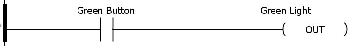
In plain English, this logic would read: ‘If the green button is energized, then energize the green light, but if the green button is NOT energized, the green light should also be de-energized’.
We can build this same statement in the Arduino IDE using a similar construction.
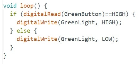
if (digitalRead(GreenButton)==HIGH) {
digitalWrite(GreenLight, HIGH);
} else {
digitalWrite(GreenLight, LOW);
}
Here is the same program displayed in the Arduino IDE to check your progress inside the void loop() function.
Normally Closed Contact and Output Coil
If the real-world button is normally closed, or if logic dictates that the contact should be used to turn off the load device, there may be a normally closed contact (or XIO) used in place of the XIC. The logic and following Arduino program will look very similar.
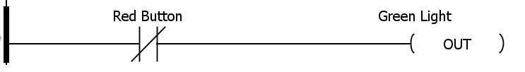
The only difference between XIC and XIO is that the comparison will be true if current is flowing, in the case of the former command, and if current ceases to flow, in the case of the latter command, so we simply compare to a low state instead of a high state.
if (digitalRead(RedButton)==LOW) {
digitalWrite(GreenLight, HIGH);
} else {
digitalWrite(GreenLight, LOW);
}
Series Contacts with an Output Coil
In the Arduino IDE, two ampersand (&&) symbols indicate the ‘AND’ comparison. If two input contacts are arranged in series, we say ‘signal 1 AND signal 2 must be energized in order for the load to energize’.
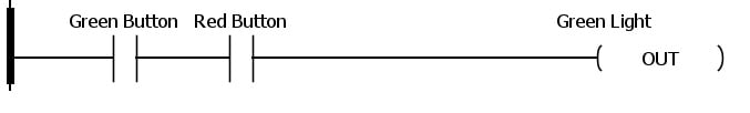
To create this logic in the Arduino IF structure, we compare both of the contacts independently.
if (digitalRead(GreenButton)==HIGH && digitalRead(RedButton)==HIGH ) {
digitalWrite(GreenLight, HIGH);
} else {
digitalWrite(GreenLight, LOW);
}
Parallel Contacts with an Output Coil
The next simplest ladder logic structure is the parallel input contacts, where either one signal OR the other must be energized for the load to energize.

In the Arduino structure, two vertical lines (called pipes, || ) complete the OR comparison.
if (digitalRead(GreenButton)==HIGH || digitalRead(RedButton)==HIGH ) {
digitalWrite(GreenLight, HIGH);
} else {
digitalWrite(GreenLight, LOW);
}
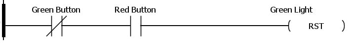
Combinational Logic - the Seal-in Circuit
Perhaps one of the most common examples of combinational series-parallel logic circuit is the ‘latch’ or seal-in circuit, which is very common for motor controls using auxiliary contacts on a contactor or motor starter.
The biggest point of confusion for this logic is the use of the output (green light in our case) as an INPUT condition. In other words, you must both energize the load, but then also check the load to see if it is on or off.
This feedback is the reason for using an auxiliary contact in a real-world version of this common control circuit. For more information about this circuit, see our article about motor control circuits.
The ladder logic appears as below.
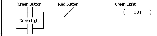
As long as we are careful to construct the IF statement in the right order, there is no limit to the complexity of a ladder line that can be built. DigitalRead can measure the value of an output or input terminal with ease.
if (( digitalRead(GreenButton)==HIGH || digitalRead(GreenLight)==HIGH ) && digitalRead(RedButton) == LOW) {
digitalWrite(GreenLight, HIGH);
} else {
digitalWrite(GreenLight, LOW);
}
What About Latching and Unlatching Coils?
In all of the previous examples, the IF statement has turned the coil ON and OFF, depending on the state of inputs. Many times, we would rather latch (set, or OTL) the output or unlatch (reset, or OTU) the output. This is revised by only providing one coil command, and removing the ‘else’ condition, as shown below.
Latch, Set, or OTL
if (digitalRead(GreenButton)==HIGH) {
digitalWrite(GreenLight, HIGH);
}
Unlatch, Reset, or OTU
if (digitalRead(GreenButton)==HIGH) {
digitalWrite(GreenLight, LOW);
}
What About Analog Values and Inequalities?
In all of the previous examples, the digital values are compared to either HIGH or LOW, since those are the only two possible states.
If you instead have a potentiometer or sensor with an analog value, the lines may easily be modified to allow inequality comparisons, like the following.
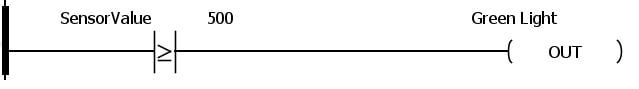
This symbol states that ‘if the sensor value rises above or equal to 500, the output should energize’.
if (analogRead(SensorVal)>=500) {
digitalWrite(GreenLight, HIGH);
} else {
digitalWrite(GreenLight, LOW);
}
Multiple Ladder Rungs
In any programming language, IF statements are always checked independently of each other. For any multiple-rung program, each line can be written as a new IF statement.
Taking it a Step Further with Subroutines
I prefer simple programs, and if I plan to use a function many times, I will prefer to write it as a subroutine.
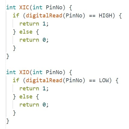
Since a normally open (or XIC) instruction should return either a TRUE or FALSE value when compared, then I would be able to write a function and call it XIC, then within that function, choose to return the TRUE (1) value if energized, and a FALSE (0) value if not energized.
Place this outside of the main void loop() function:
int XIC(int PinNumber) {
if (digitalRead(PinNumber)==HIGH) {
return 1;
} else {
return 0;
}
Now, when we need to use a normally open or XIC instruction, we simply need to write XIC and provide the name of the pin (or ‘tag’) we wish to use. Since the comparison is already done in the subroutine, we only need to call the XIC subroutine to return the TRUE or FALSE comparison value, and so we no longer need to use the '==' comparator.
Immediate simplification!
if (XIC(GreenButton)) {
digitalWrite(GreenLight, HIGH);
} else {
digitalWrite(GreenLight, LOW);
}
We can do the same for our entire remaining set of XIC, XIO, and for the output OTE, OTL, and OTU like the following:
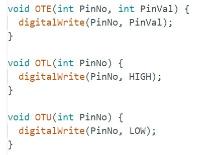
With these subroutines provided, a few of the previous sample codes can be rewritten to look like the following.
if (XIC(GreenButton)) {
OTE(GreenLight, HIGH);
} else {
OTE(GreenLight, LOW);
}

if (XIC(GreenButton) && XIO(RedButton)) {
OTL(GreenLight);
}
if (XIO(GreenButton) && XIC(RedButton)) {
OTU(GreenLight);
}
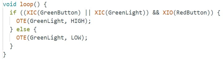
Finally, the combinational latching circuit can be easily built, with the actual screenshot of the code shown below to illustrate how the colors should appear in the current IDE version.

PLC to Arduino
The two platforms are very different, designed for different environments and uses. However, the simplicity of PLC programs can make it quite easy to adapt those ladder logic codes to the simple IF structures of a text-based language.
Explore what you can accomplish with these rungs, and if you design any new commands and subroutines, add them into the comments below to share your experience with others who wish to learn this new skill.
Want to test your knowledge of PLCs? You think you N.O. a lot about ladder logic? Are you a normally-open or normally-closed minded engineer?
Check out our PLC Programming worksheet!


In the section “Series Contacts with an Output Coil”, GreenButton is being read twice. Shouldn’t it be:
if (digitalRead(GreenButton)==HIGH && digitalRead(RedButton)==HIGH ) {
And in the next section “Parallel Contacts with an Output Coil”, again the GreenButton is being read twice. Shouldn’t it be:
if (digitalRead(GreenButton)==HIGH || digitalRead(RedButton)==HIGH ) {