 Facebook
 Google
 GitHub
 Linkedin
Introduction to Advanced Motor Control Circuits
This article looks at a few of the more advanced motor control circuits for a three-phase motor.
In a previous article, we discussed a few basic circuits to drive three-phase motors using contactors and simple push-button devices. There is a huge variety of control situations and respective circuits, and even a short series of articles can’t possibly cover all of them. Presented here are a few of the slightly more advanced control circuits.

Figure 1. Advanced motor control circuits utilize multiple components.
The previously published basic motor control circuit article presented a few simple circuits to drive contactors to run motors. Those circuits can drive both single-direction and reversible contactors, and they work for contactor coils from 24 vDC up to 230 vAC (as long as the buttons and controls are rated for such voltage!)
The following circuits are slightly more advanced, but it’s important to remember that VFDs can be easily employed for anything from basic to complicated. The price is a bit higher than for manual control devices and contactors, but the extra capability can be well worth the cost. Connecting the VFD to those devices is better left to other articles since the topic changes gears quite a bit.
Are you a motor troubleshooting expert? Quiz yourself with our (no pressure) worksheet!
Run/Jog Toggle
The jogging function of a machine is commonly used to set a position, or perhaps reverse a motor a short distance to clear a jam or reach a certain potion before beginning a cycle. In some cases, jogging can bypass certain safety considerations, and for that reason, jogging is considered a movement action (usually at a lower speed) that must be momentary. In other words, for movement to occur, the start button must be pressed and held. Releasing the start button should also stop the motor.
To construct this circuit, any of the basic circuits may be used for single-direction or reversing. A second quarter-turn switch is used in series with the auxiliary contact branch. The quarter-turn switch can either allow the auxiliary contact to latch the circuit, providing our original start/stop control. Or, it can disable the latch so that the start button MUST be held to continue motion.

Figure 2. This schematic shows the Run/Jog Toggle switch placed in series with the latching auxiliary contact. In the lower image, a relay coil and contact set may be used in exactly the same configuration.
Multiple On/Off Controls
Sometimes there are multiple operator stations that must be able to start and stop the motor. Series and parallel connections are useful, but care must be taken for those devices which are normally open (NO) or closed (NC). To allow multiple start controls, which are NO, they must be in parallel branches just like the auxiliary latching contact. Any NC Stop controls must be in series, preventing the flow by pressing any of those stop buttons.

Figure 3. Multiple operator stations can be wired in parallel for all NO Start controls, and series for any NC Stop controls, just like any standard E-Stop circuit.
Master On/Off Switch
A single control device may be used to prevent operation of the motors in the case of multiple stations. Perhaps one operator turned the motor off and wants to perform maintenance. There should be a single location from which the entire control or power circuit can be disabled and locked out.
This circuit adds a switch or latching E-Stop button which prevents any operator from turning on the motor circuit from another location. A relay coil is activated by this master switch control. A contact of that relay acts as another Stop control. If the relay is de-energized, the starter coil will immediately turn off. Of course, this same circuit can be used even if there is just one operator station.
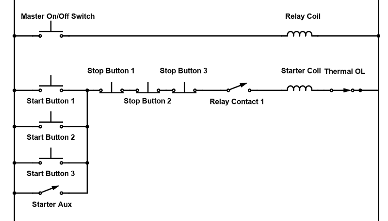
Figure 4. One master latching control (quarter-turn switch or E-Stop) allows a single relay contact to inhibit input from any of the operator stations.
Adding Indicators
Many pushbuttons are illuminated, which means they have a light bulb or LED inside to indicate whether the control is active or not. For start/stop circuits, the start button will be illuminated when the motor is running, and the stop button lights up when the motor is stopped. This can also help with troubleshooting, showing the operator that the control voltage is responding, so any motor problems must be located in the power circuit.
This circuit must use a multi-pole relay since four responses must be taken:
- Start/stop latching
- Start button light
- Stop button light
- Starter coil
Alternatively, if the starter has two NO aux contacts, and one NC aux contact, the relay can be omitted. In the diagram, simply replace the relay coil with the starter coil and use aux contacts instead of relay contacts. Now the entire fourth line may be omitted.

Figure 5. Indicator lights can show whether the coil is energized or not. These might be stack lights rather than illuminated buttons.
Achieving Speed Control
If variable speed is a requirement, it is wise to consider using a variable frequency drive (VFD) instead. Manipulating the control side voltage can only result in two options: pulsing the contactor on/off very quickly (which would destroy the contactor) or lowering the voltage with a device other than a contactor. Lowering the voltage will weaken the motor and cause it to come to stop, not just slow down.
The VFD manipulates the power side voltage, providing an entirely different method of speed control.
Interested in more content about motors? We have plenty to choose from!
Articles:
- 3-phase Motor Types: Synchronous and Induction Motors
- Understanding Delta Wound Motors for Industrial Applications
- Common Motor Windings and Wiring for Three-Phase Motors
- Brushed vs. Brushless DC Motors
- Field-oriented Control (Vector Control) for Brushless DC Motors
Textbook:


in fig.2,3,4,5 the contact for the “thermal OL” should be NC ...?