 Facebook
 Google
 GitHub
 Linkedin
Understanding Delta-Wound Three-Phase Motors for Industrial Applications
There are two types of winding designs inside three-phase industrial motors: Wye and Delta. Although the motors and connections look similar on the outside, this article discusses the internal construction for Delta wound motors.
Check out Control Automation's exclusive eBook on motor wiring

Industrial motors are usually supplied from a three-phase voltage source. The three-phase line inputs attach to windings inside the motor to generate magnetic fields that drive the rotor. There are two types of winding designs inside these motors: Wye and Delta. Although the motors and connections look similar on the outside, the internal construction creates some unique differences to be aware of.
Most people could probably live their whole lives without knowing or caring about the difference between wye and delta windings. However, if you can visualize how the coils are arranged, it can help to make better sense of multimeter resistance tests and aid in troubleshooting and installation.
Differentiating Delta vs. Wye Motor Wiring Systems
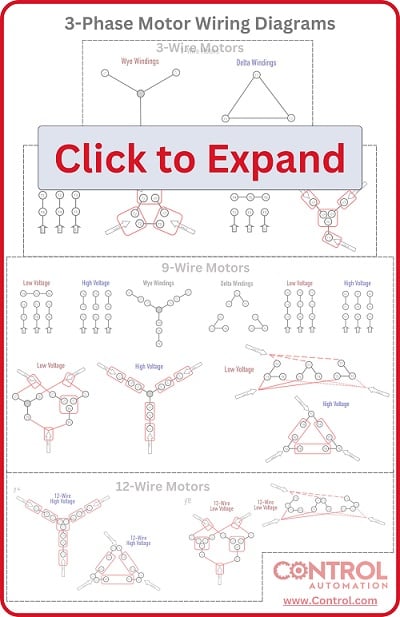
Of all the three-phase motors that exist for industrial applications, they can all be simplified into either a Wye or Delta internal wiring system. These terms refer to the schematic image of the shape of the coils inside. In reality, both wiring schemes arrange six independent coils around the perimeter of the motor — the electrician chooses how the electricity is passed between the coils.
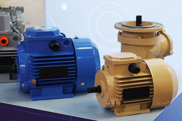
Figure 1. Of all the three-phase motors that exist for industrial applications, they can be simplified into either Wye or Delta internal wiring systems.
There is no strict declaration of when a certain wiring style is preferred. It is common to see Wye arrangements used for lower horsepower motors since the winding resistance is a bit higher due to internal series configurations. As a result of the series windings, Wye motors have higher resistance and less energy conversion than a Delta counterpart. There are many construction factors that can create useful motors of either type for a large range of horsepower outputs.
Are you a motor troubleshooting expert? Quiz yourself with our (no pressure) worksheet!
In both wiring scenarios, the motors can be configured for low voltage inputs between 208-240 volts, or for high voltage which is usually around 440-480 volts. The exact voltage depends on tolerance, geographical standards, and the supply transformer configuration. That exact voltage can slightly change the horsepower output, but most motors have only those two wiring choices - low or high voltage.
The Wye configuration is easier to think about in a mathematical sense since the arrangement of the coils is quite straightforward. Delta arrangements, on the other hand, are a bit harder to mentally picture when only a wiring terminal connection diagram is provided.
Delta Wound Motor Diagram
The use of the term Delta refers to the Greek letter resembling a triangle. The schematic arrangement of the Delta motor is this triangle pattern, except it’s broken on each side to allow user-customized connections for high or low voltage.
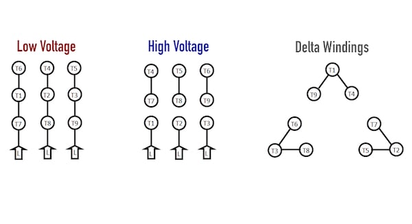
Figure 2. Schematic arrangement of low, high, and Delta motor windings.
The terminal connections and the internal arrangement of a typical nine-lead Delta winding motor.
As with any three-phase motor, those six windings (which appear as the straight lines on the diagram) are distributed around the perimeter of the motor to create a balanced rotation.
A previous article about Wye-wound motors described the need for lower resistance with lower voltage supplies. This is equally true in the Delta arrangement. In a short summary, if the voltage is lowered from 480 to 240 volts (half the voltage), the current must double in order to create equal horsepower. However, if the voltage has been cut in half, the resistance must be cut to one quarter of the previous amount in order to produce twice the current. This must be true in the case of both motors — high voltage wiring should have 4x the resistance of low voltage wiring.
Delta Motor Wiring for High Voltage
It’s a bit backward perhaps, but we’ll cover the high voltage wiring scheme first. The diagram below shows the required lead connections for high voltage.
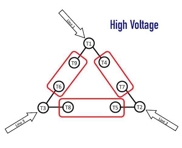
Figure 3. Required lead connections for delta motor windings.
When the high voltage connections are made, this diagram shows the resulting connections.
Incidentally, the terminal connections are exactly the same for high voltage in both the Wye and Delta motor configurations!
In the Wye motor, high voltage resulted in a connection of the large Wye with coils in series. In contrast, inside a Delta motor, the high voltage results in a large Delta shape. However, the coils are not simply in series anymore. What results is a series-parallel combination circuit.
Imagine yourself being an electron, following the current path from Line 1 to Line 2. Two different current paths exist.
First, current may travel through T1-T4 then straight to T7-T2 directly. This equates to two identical windings in series.
Second, it may travel through the path T1-T9 then to T6-T3-T8 and finally to T5-T2. This creates the equivalent of four windings in series.
If two parallel paths exist, one having the resistance of two windings, the other with four windings, the result is the parallel combination of 2R || 4R which yields 4/3R, or 1.33 x the value of one winding.
Compare this to the value found in the high voltage scheme for a Wye motor. In a Wye motor, the value is four times the resistance of one winding alone. As you can imagine, this yields much more current (and therefore power output) in the Delta motor, assuming the input voltage and other parameters are equal.
Delta Motor Wiring for Low Voltage
Low voltage is saved for last due to the complexity of the math required to analyze the winding resistance.
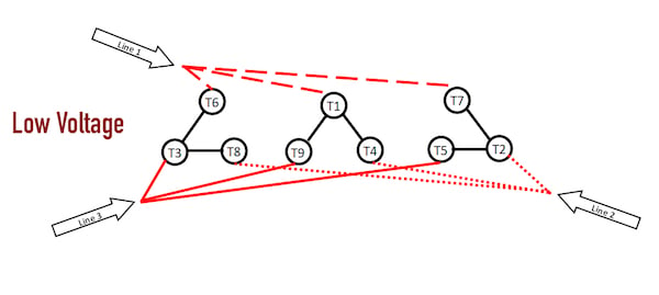
Figure 4. Lead connections for low-voltage Delta wiring.
When the low voltage connections are made, this diagram shows the resulting connections.
The image above has been rearranged to simplify the situation as much as possible. Each line input is connected to one of the small Delta triangles inside the motor. This setup only requires three connections, so if you open up a motor casing and find only three-wire nuts, you have identified a low-voltage Delta motor.
In this scheme, imagine Line 1 to Line 2. There are three different possible current paths in this case, so we can list each option.
- T1-T4 through one winding.
- T7-T2 through one winding
- The parallel of T6-T3 and T1-T9 and then through the parallel of T3-T8 and T5-T2. This yields a series of two sets of parallel windings - the overall result is one winding equivalent.
When these three paths are placed in parallel with each other, the final resistance is equal to 1/3R or 0.33 x the value of one winding. As expected, this is exactly ¼ of the value of the resistance in the high-voltage configuration.
Wiring Diagrams for Three-phase Motors
For most projects, it really doesn’t matter what the internal wiring setup might be. If you have a five HP motor wired for high voltage, that motor is appropriate for any 480-volt application that needs five horsepower. You don’t need to worry about how the manufacturer bonded the wires inside. It is a good practice for any electrician to understand why something works, not simply how to make it work — it pays great dividends to know not only the reason for proper operation but also the reason for failures.
Interested in more content about motors? We have plenty to choose from!
Articles:
- Comparing Single-Phase and Three-Phase Motors
- 3-phase Motor Types: Synchronous and Induction Motors
- Common Motor Windings and Wiring for Three-Phase Motors
- Brushed vs. Brushless DC Motors
- Field-oriented Control (Vector Control) for Brushless DC Motors
- Teardown: What’s Inside a 3-Phase Induction Motor?
Textbook:
Related Content


Delta motor low voltage wiring diagram
Figure 4. Lead connections for low-voltage Delta wiring In this case, can I use a VFD to run this 380 volt motor?