Facebook
 Google
 GitHub
 Linkedin
TRi PLC Fx Series Tutorial: Getting Started with Ladder Logic
Learn how to connect, wire, and program a TRi PLC Fx controller in this step-by-step tutorial.
Triangle Research International offers a unique approach to control systems with its open-board Fx series PLCs. In this hands-on tutorial, we walk through the essentials of connecting, wiring, and programming one of these controllers. From hardware setup to downloading a simple program via serial communication, this guide provides a practical starting point for engineers exploring customizable PLC platforms for OEM and embedded automation applications.
Although the exposed PCB may look unfamiliar to many engineers in the automation and control system industry, we must remember that a PLC is simply the executor of logic functions with inputs and outputs that interact with the real world. There are many PLC designs in existence, all with varying degrees of protection against environmental factors and operator mishandling, and these factors are always considered during the design process.
What is the Fx Series From TRi PLC?
As always, we’ll start with the hardware. This PLC series already contains most of the necessary functionality for projects ranging from simple to fairly complex. These controllers include Ethernet, RS-232, 2x RS-485, and both digital and analog I/O, in quantities depending on the exact model number. The number of I/O points can be easily expanded with Modbus networking support.
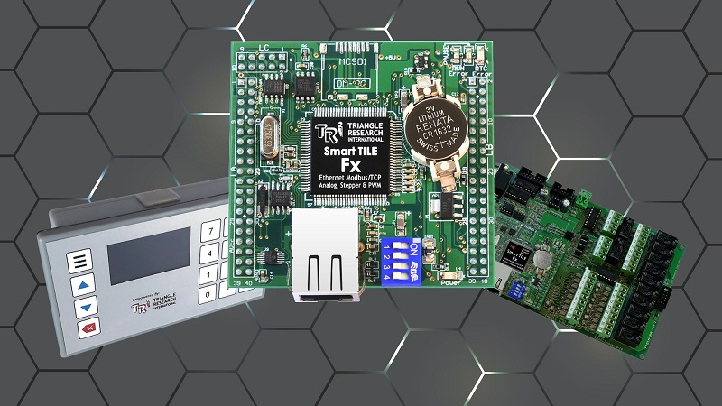
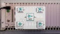
Figure 1. TRi PLC products, including the Wx Series (left), the SmartTILE controller (middle), and the Fx Series carrier board (right).
This exact model is the Fx2424, which has 24 digital input and digital output points, as well as 8 analog inputs and 4 analog outputs.
A few noteworthy details that will be important to a programmer:
- The digital inputs are sourcing, so all sensors must be of the sinking NPN type, and pushbuttons/switches must be connected to the 0 VDC supply to complete the circuit.
- The inputs are internally supplied by the 24 VDC supply, so there is no ‘common’ input terminal, as is familiar on most PLCs.
- The outputs are sinking, which means the load devices must be powered directly by their respective power supplies, not by the PLC.
- Note: sinking outputs are a huge advantage when mixed-load devices may require the use of 24, 12, and 5 volt devices. If the outputs are sourcing, they can only provide one single voltage, usually 24 volts.
- The analog I/O is designed to accommodate 0-5 volts via a DB15 cable. To use 0-10 volt or 4-20 mA devices, a few resistor networks can be employed.
Project Hardware
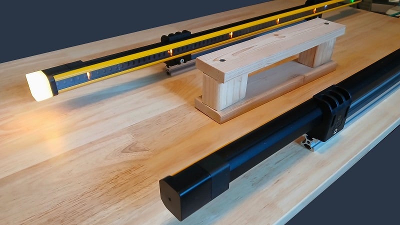
This introductory tutorial will use RS-232 for the connection, plus one input and one output device. For the connection, a standard USB-to-Serial converter cable. In the past, I have had mixed results with various cables, and some chipsets (such as the CH340) do not always work, so I use a Prolific chipset cable, and it works well. For the I/O devices, I chose a selector switch and a mechanical relay. Aside from these parts, the setup needs only an industrial supply and various lengths of wire for the I/O devices.
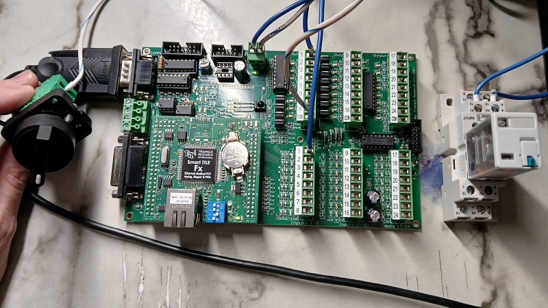
Figure 2. The complete project hardware: power, a serial cable, an input switch (left), and a relay (right).
1) Power the Board
Connect power to the header near the power LED. This header is marked with +24 V and 0 V.
2) Connect the Switch
Since the inputs are sourcing, we must run a wire from 0V of the supply to the switch, then out from the switch to the terminal marked 1 on the Inputs 1-8 header bank. Again, no common power connection is needed, since it receives a small amount of input current from the power header.
If the PLC and the switch are powered from the same supply, this will work just fine as-is. If they are on different power supplies, you must connect the 0 V terminals of both supplies to establish a common return path.
3) Connect the Relay
Since the outputs are sinking, we run a wire from +24 V of the supply to terminal A1 of the relay, then out from the relay terminal A2 to terminal 1 of the ‘Outputs 1-8’ header.
Since outputs require more current than the inputs, a common connection is required for the outputs. This COM terminal on the output header must be connected to 0 V of the load power supply.
Software
The Fx PLCs use the i-TRiLOGI software version 7.5 or later (7.53 as of this writing). Download and install the software according to the instructions; there are a few installation directories and dependency notes.
Connect to the PLC
Although Ethernet is a common standard, this tutorial will employ the simpler RS-232 serial port. Ethernet configuration will be discussed in future tutorials.
Use a USB-to-Serial cable and connect COMM1 of the PLC to your computer. A device driver should automatically install on a Windows PC and be assigned a COM port number. Check your device manager to verify the COM port number.
Open the i-TRiLOGI software and open the Controller menu at the top. Select Connect to Server. From the listed options, select Serial/USB Port, then Configure Serial Port.
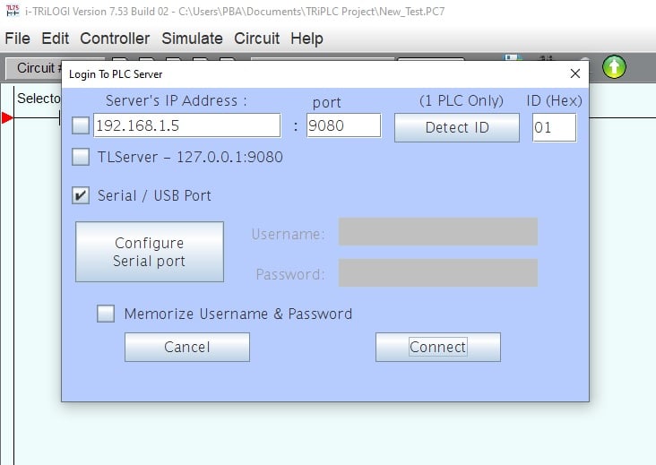
Figure 3. Connecting to the PLC.
In this Serial Setup window, you may need to change the port if several devices are connected, but it should already be properly selected. Click Open Port, and the response string window should reflect that the port was opened.
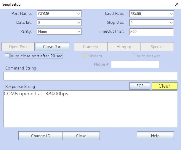
Figure 4. Opening the serial COM port.
Now close the Serial Setup window and the Detect ID window. If the hex ID autofills with a number, you can connect to the PLC.
Write a Simple Program
To write a simple ladder program, double-click in the green workspace near the red arrow, indicating the top ladder rung. At this point, a menu of commands will open along the top bar.
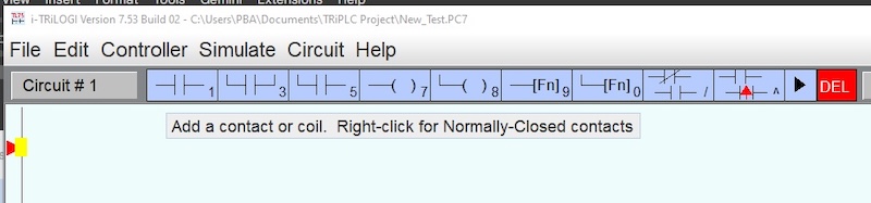
Figure 5. Adding instructions to the ladder rung.
Click on the normally open contact numbered 1 (alternatively, just press 1 on the keyboard). The I/O table will open, and you may select from an already-named terminal or assign a new name to a new terminal for convenience. If you chose the wrong terminal, no problem. Simply click to highlight the command, right-click, and rename or pick a new point from the I/O table.
Repeat this process to add an output coil (or press 7). The points can be selected from the table or renamed in a similar manner to the inputs.
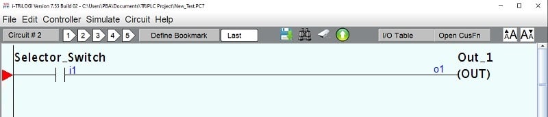
Figure 6. Complete program.
After the program finishes, select Controller -> Program Transfer to PLC from the menu bar. Depending on your exact order of operations, you may need to identify the serial port again (see paragraphs 3-4 in the previous section). If successful, you can transfer the program, and the window should report a successful transfer.
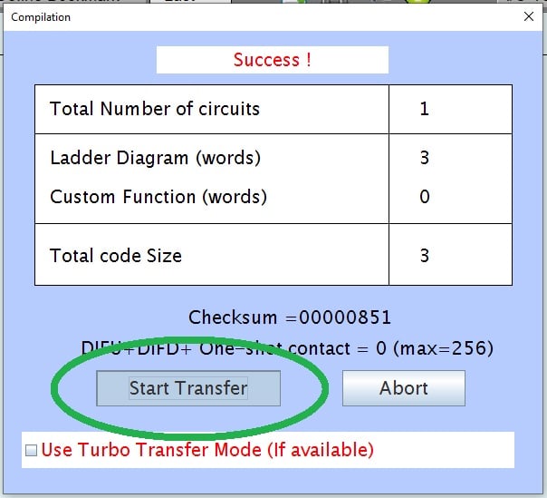
Figure 7. Program transfer to PLC.
Next Steps
This example is only the simplest possible program that we could design for a serially connected PLC. In future articles, we’ll explore analog I/O, Ethernet networking, and more advanced commands, including BASIC functions that can be built into custom program elements.