Facebook
 Google
 GitHub
 Linkedin
Electronic Datasheet (EDS) Files: Why do We Use Them?
Many control product manufacturers offer these downloadable ‘EDS files’ for peripheral equipment, but what exactly is an EDS, and how can they aid in the development of a project?
Sometimes, you simply need to connect a controller from Company A to a peripheral device from Company B.
Conflicting compatibility is certainly a situation everyone wants to avoid, but the only way to avoid such a situation is to either build a brand-new (greenfield) development or possess an unlimited upgrade budget with the ability to purchase an entire set of compatible equipment. Such a hope is unrealistic for most engineers.
Thus, we are left with the challenge of connecting equipment from multiple generations, conflicting protocols, and different manufacturers with the hope that they might work together.
Implicit and Explicit Messaging
One way to manage this problem of compatibility is to first ensure that all devices can at least communicate on the same wavelength, that is, protocol. For many modern facilities, this means Ethernet or Profinet. With this similar baseline, the messages should safely arrive from source to destination, the only challenge remains of interpreting the message.
Setting up a messaging service on a control device can be a daunting task. There are several unknown elements such as the size of the messages (are they bytes, integers, or perhaps floats?), the number of messages (is it just a few, an array of hundreds?), how many are reserved for inputs, how many for outputs? Obviously, just a few wrong choices and we may as well have not even attempted in the first place.
Generic Ethernet Module Setup
For setting up a generic device on an Ethernet network, several pieces of data must be known, as mentioned before.
In this example, we’ll discuss a Rockwell PowerFlex module, with the information provided being applicable to any controller, from any manufacturer with an Ethernet-capable port. This information is pulled directly from the product user manual (starting on page 55 for specific reference), as it should be with nearly any device.

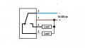
Figure 1. Generic Ethernet setup with data type, assembly instance, and size information.
As we can see from the image in the Studio 5000 software Generic Ethernet Module setup, the following information is required:
-
Comm (data type) Format, which may be 8, 16, or 32 bits.
-
Assembly Instance, which must be provided by the manufacturer for I/O and Config information
-
Size refers to the number of data types that are required for proper communication. They must be included, even if the value is zero.
Knowing this information, I could install this VFD on any networked controller with a generic Ethernet capability.
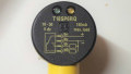
In a second example (Automation Direct), showing a slightly different set of input panels, I can add a message for I/O information. It asks for an assembly Instance, data type, a name for the tags (Data Array), and a number of elements. As we saw previously, we have this information from the user manual, so using this VFD with this PLC is not too difficult.

Figure 2. Ethernet module entry for an Automation Direct PLC.
What’s Wrong with Adding a Generic Ethernet Module?
In the example above, I have already located the module details in the manual and have provided screenshots of both corresponding systems to make this easier to visualize. But without this information, and tasked with building this project alone, seeking the information might prove to be a challenge.
In fact, it’s usually much harder than it sounds.
In order to quickly set up a compatible communication channel, you must be confident that when opening up that “New Generic Ethernet Module” dialogue, you will be able to find all the required information.
Not every control engineer is keen on sorting through documentation to find Ethernet messaging attributes, and I don’t blame you.
Fortunately, the manufacturers don’t blame you either.
Electronic Datasheets (EDS)
To begin with, the datasheets already contain the information we need to set up the manual communication, so these EDS files literally are just a virtual re-creation of the tables and data. If those numbers can be filled into the appropriate spots in the Ethernet (or other) module creation tab, the hard work is done.
When you locate and download an EDS, you now have a text file of the assembly and data information, but you also have a whole lot more.
For this example, I downloaded an EDS for a Balluff IO-Link Ethernet hub. This should be able to connect to an Ethernet controller and share I/O data. This is not unique to this product, it’s only a sample.
The EDS is a zipped folder that contains two items. The previously mentioned data file and a small thumbnail image of the device, so that when added to the project, I can see what I am working with. The generic Ethernet icon contains no such specific image.
What’s Inside an EDS File?
The good news here is that you really don’t need to understand all of this. It should not be edited. But if you want to get a quick glimpse of what’s inside an EDS file, here is an example:

Figure 3. Extract of EDS file text.
This is the text editor view of the tabulated data for one of the parameters which can be shared between devices.
Remember when we created the Generic Ethernet Module? We could assign a number of bytes or integers to the Input data array, but we really had to guess or discover what each one of those meant. For a VFD, one should turn it on, one should assign the direction, yet others should command the speed, but we would have to manually locate those parameters and assign the descriptive names.
In looking at this parameter, we can see a data type (hex coded), a data size of 1 byte (8 bits), and a name.
When a new IO-Link hub device is created in my project using this EDS, I will look into my tag database and expect to see a single tag, one byte (or SINT) in size named ‘Power status’. Most likely, we would assume this to be a value of either 0 or 1, but it may also contain fault codes.
Isn’t that nice—we don’t need to discover the task of each input and output byte. Good news, because there are a LOT of them.
390 of them, to be specific. Some are grouped into sets of 16 bits which use two 8-bit bytes, but there are 390 bytes, just in the “Input” assembly. Take a look at Param4 below. This is the same Parameter 4 we saw in Figure 3, the ‘Power status’. Most are reserved for the IO-Link Input Data, as expected.

Figure 4. Input ‘Assembly Instance’, already populated with proper size and applicable tag names.
Finding and Using EDS Files
No doubt EDS files will make programming much easier. To locate them, first try the manufacturer’s website or customer portal. Even a chat with a customer service rep can be faster and less stressful than trying various configurations to finally make something work with the generic manual approach.
Thanks, OEMs, for designing equipment with both compatibility and predefined parameters. Speaking for all of the engineers, we appreciate it.
Featured image used courtesy of Canva
Related Content