 Facebook
 Google
 GitHub
 Linkedin
Designing a Custom Machine Alarm System: From PLC to HMI
Creating custom alarm systems can be complicated and overwhelming, but they can also be very beneficial for equipment builders and integrators. Follow along as we build a custom alarm handling system.
Automation equipment alarms are usually triggered when an event that should have occurred did not, such as a servo positioning device not reaching its commanded position, or a robot not completing a task. These alarms must stop the equipment’s sequence from continuing and inform the equipment user that something unexpected has occurred within the machine and needs to be addressed before the machine will continue.
Logic for Machine Alarms
The logic to trigger alarms and stop sequences, as well as how the messages are displayed to the user, are likely to vary depending on the control system being used. Most PLC and HMI applications will have some kind of internal alarm handling feature, but it is often restrictive in appearance and how alarms are handled. For these reasons, most equipment manufacturers will develop their alarm handling procedures.
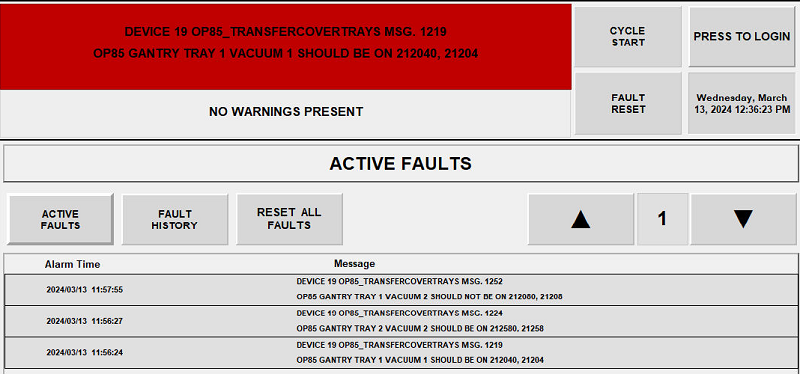
Figure 1. A sample fault screen from an HMI. Image used courtesy of the author
Alarm Methods in The HMI
Alarms need to do two things; they need to stop the sequence and display a message to the operator. To display a changing message on an HMI, you need to use a message list that provides a range of numbers associated with respective error messages. When the connected tag has a value, the HMI component will display the message that corresponds to that value. Each HMI development environment will have a different version of a message list.
- In WinCC (Siemens HMI environment), there is an option to create a text list that can be connected to tags in the PLC.
- In FactoryTalk View (Rockwell Automation) a local message display is used to connect a text list to a PLC tag.
- Aveva Edge, which is a system-agnostic HMI application, also uses message lists and message displays.
Creating error handling within the HMI itself allows for virtually endless flexibility when creating an alarm display feature on your HMI screen. Special colors can even be added, depending on the value of the alarm for example, alarms ranging from 1 to 1000 might display a red indicator, whereas alarms ranging from 2000 to 4000 could be yellow, or additional tags can be used to drive the same functionally. Special buttons can be added for retry, acknowledge, or clear error functions, and visibility animations or user-level functions can also be added to those buttons.
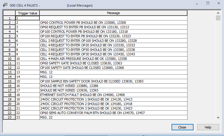
Figure 2. List of faults by number and by descriptive label. Image used courtesy of the author
In some development environments, those lists are stored in a local directory and can be edited with a simple text editor or CSV editor. Aveva Edge stores these message lists as CSV files within the project directory. This allows developers to create applications or Excel macros that can update and refine these message lists with little user intervention.

Figure 3. HMI button interaction for fault codes. Image used courtesy of the author
Alarm Methods in The PLC
Once we have our HMI developed, we can now focus on how we are going to drive the alarm number from our PLC to the HMI. A common method is to assign every bit within a double word (or DINT) to its own alarm.
For each alarm, the programmer would set up the conditions required to activate that alarm. Those conditions would then set one of the bits within the DINT from 0 to 1. If multiple bits come on at once, each one can be displayed on the HMI in a list format or with a scroll feature. The double word is then decoded into a single integer value and sent to the HMI to display the correct alarm. When the user acknowledges the alarm and corrects the fault conditions, the variable can simply be cleared. If the conditions are not satisfied to clear the alarm, then the alarm will be set again.
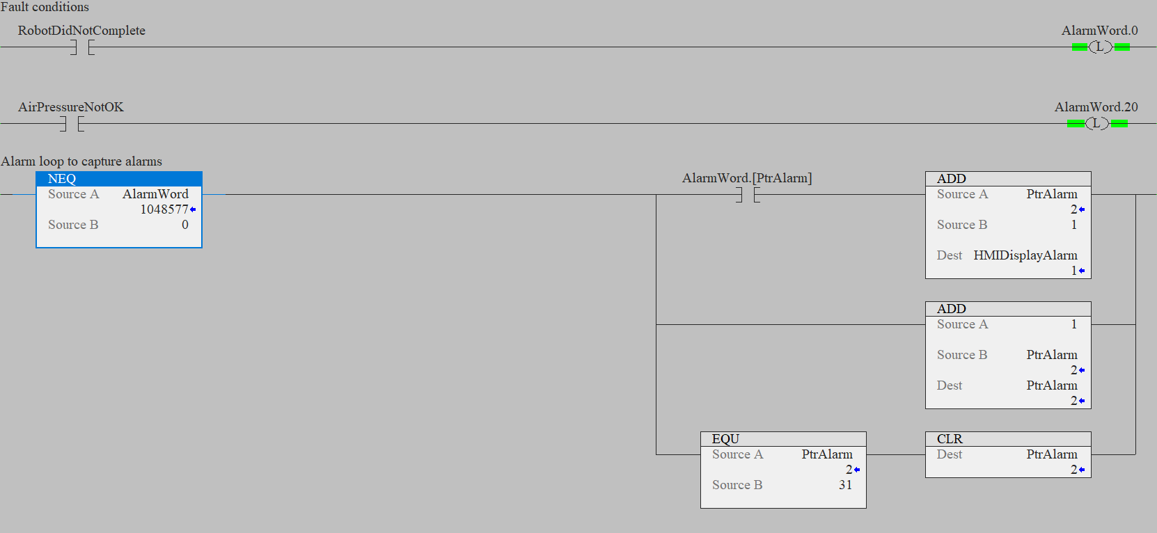
Figure 4. Alarm bits are set, and if a fault is present (AlarmWord is not zero), a fault counter is incremented. Image used courtesy of the author
Decoding The DWord: Booleans to Integer
The decoding process is essentially converting all the individual bits within a word to a single numerical value. An easy method is to simply loop through every bit in a DINT variable, using an open contact addressed to the variable bit inside the DINT. When true, we can move the loop pointer into a display variable. So if the second bit within the AlarmWord variable comes on, the HMI will display the alarm message that is assigned to value 2. The same is true if bit 20 comes on, the HMI will display the message associated with value 20. This method, using a DINT, will give you 32 alarms. For a 16-bit PLC, an INT may be preferred, which would provide 16 alarms.

Figure 5. Alarm loops in an array pattern. Image used courtesy of the author
If you need more alarms, or if you want to display multiple alarms at once, then turn your AlarmWord into an array and loop through both the AlarmWord array and the bit level of the index. As each Alarm is detected, insert the alarm number into the next empty index of your HMI display alarm variable.
A FIFO (first in, first out) function can help load up arrays with values, or you can do multiple loops. This example will load up to ten alarms into a variable that is mapped to the HMI alarm screen. All ten alarms can be shown at one time.

Figure 6. HMIs are often the primary source of information for operators. Make sure the message is clear. Image used courtesy of Rockwell Automation
Helpful Alarm Tips
Alarms are used by maintenance staff and integrators to debug and diagnose problems. When equipment stops, a common method to troubleshoot the issue is to follow the alarm prompts, so making your alarms easy to find will help not only the integrator team but also the end customers.
Try keeping your alarms in routines named “Alarms” or “Device Faults” This way, when a particular device displays an alarm, users will know where to look. It's also helpful to keep device-specific alarms together with the logic that controls that device. For example, a vision system might have a series of alarms named: “Failed Inspection,” “Offline,” or “Inspection Didn’t Complete.” Keeping the control logic and alarms together in one task makes for easy multiple deployments into other projects or other sections of code.

Figure 7. Each task contains routines for control as well as for alarm handling. Image used courtesy of the author
The Final Result
By using the method we've described, you can develop flexible and dynamic alarm handling systems that can be used with virtually any control system and HMI application. If you are an equipment builder whose customers often dictate which HMI application and which PLC you can use, developing a consistent custom alarm handling system can be very beneficial.


Great article! Your detailed guide on designing a custom machine alarm system from PLC to HMI is incredibly informative and well-explained. It’s an invaluable resource for engineers looking to enhance their automation systems.