Facebook
 Google
 GitHub
 Linkedin
Connecting Multiple PLCs to an HMI
Learn the basics of connecting multiple PLCs to an HMI using various data types.
Most entry-level training for control systems includes programmable logic controllers (PLCs)—ladder programming, wiring inputs and outputs, as well as tag databases and the various data types. Human-machine interface (HMI) programming is a level above this PLC knowledge, but understanding those tag databases in various PLCs can simplify the HMI design process.
One of my favorite “experimentation” projects in my own control system setups is to find a new device and figure out how to interface it into a larger system. Obviously, these devices come from a wide variety of vendors, and all must work together.
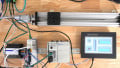
Most common touchscreen HMIs are designed for just this kind of application, allowing multiple systems to simultaneously operate and display data on a central operator screen.

Figure 1. Multiple PLCs networked with a single HMI
Programming an HMI involves two main components. First, and perhaps most critical, is understanding graphic objects such as buttons, number and text entry fields, graphical data displays, and others. It’s usually fairly simple to follow online tutorials for this step.
The other step is what we might call “behind the scenes,” where the objects on the screen actually read or manipulate tags inside the PLC. This may not be so simple, since every PLC has a different tag database structure.
HMI Data Types
Every PLC has access to the main “atomic” data types, but they can appear differently.
Begin with the boolean, or BOOL type. This is a single bit, often an internal status, perhaps a timer or counter termination bit, or an input/output tag.
A discrete data type is simply a bool, and needs no further addressing from the controller. If this bool is called “Temp_Alarm_Status”, it can only be ON or OFF. However, any integer can also describe a boolean data bit. In this case, we must specify not only the integer’s name (or memory location), but also which of those integer’s bits is required.
Although every integer can be broken down into its component bits, not all of them should be used in this manner. One way to consider this difference is whether the integer represents a value—like an analog temperature or pressure. If so, there is no reason to use this integer in its boolean components. However, if the integer is a string of discrete bits of information, such as data coming across a network connection, or an I/O module consisting of many bools, it would make sense to consider the importance of each discrete bit.

Figure 2. A 32-bit DINT named “Current_Temp” defined in the HMI software (Left) and similarly defined in the RSLogix Controller Tags (right)
Floating Point (Real) and Char (String) values cannot be expressed as individual bits. Although they are technically built out of 32 bits, or 8 bits for a char, they no longer use each bit as a separate binary place value, like in an integer. There would be no meaningful information extracted from the booleans of these data types.
Naturally, those integers, floats, and strings are used everywhere in HMI programs, contributing values.
PLC Communication Considerations
Within the scope of a single article, I cannot provide a tutorial for every HMI environment and every subject PLC. However, there are numerous similar considerations no matter which software you use.
First: the communication protocol. HMIs are designed with a wide variety of network interfaces—the standard being Ethernet, RS-232, or RS-485, but often with adapters for several others. You must be able to select your own PLC and be aware of its network connection protocol. Finally, most screens are limited in the number of simultaneous connections, but they usually allow more than just one.

Figure 3. Various HMI communication and programming ports
The target PLC will describe its tags with various methods. Tags (variables created in the PLC) are stored within a numbered register address and might be a single bit within that register. Some PLC varieties require you to know this specific address number.
Siemens is one example. To point to a single bool, you will need to specify an input, output, or memory, then a register address (perhaps 15), then a bit from that register (like 3). In this example, the bool would be M15.3. An integer would not include the bits themselves, so it might simply be M15.
Some PLCs may have an ordered method of assigning a numeric value to each newly created tag. They may each have a prefix to denote the data type. An example of a structure like this is from the Automation Direct Productivity PLC line, where the first created boolean would be C-000001 (C being the designator for a boolean value). A 32-bit integer may be S32-000001, etc.
In Allen Bradley Compact/ControlLogix architecture, the structure is by tag name. Each tag created by the user has a unique name, rather than a number. This can simplify the process, as long as the PLC designer assigned logical names to the tags. An example of this tag name method is illustrated in Fig 2.

Figure 4. The network switch allows multiple machines to connect to an HMI with only a single Ethernet port
Recap
To assign multiple PLCs to a single HMI, the biggest obstacle is understanding how different tag databases are organized within the respective PLCs. When adding those tags to the HMI database, select the correct PLC device, add proper tags, and the data transmission between the screen and the controller should be automatic.
With a solid understanding of this process, an HMI should be able to monitor and control some pretty impressive systems.