 Facebook
 Google
 GitHub
 Linkedin
Understanding Floating Point Numbers in PLC Programming
There are three main types of numeric values that must be handled by a PLC: boolean, integers, and floating point. These last floating-point values can create the most confusion for programmers and technicians.
Any digital control system containing a processor is designed to receive input values, calculate solutions using those values, then provide outputs to other devices using those calculations. The numbers used at each step in this process must be carefully chosen — not only precise enough to provide the correct output values but also small enough so as to not consume too much of the limited available memory space.
Main Categories of Digital Numbers
Digital numbers fit within three main categories of values:
-
Single-bit Binary Numbers
-
Multiple-bit Integers
-
Floating Point Digital Numbers
Single-bit boolean numbers can only hold a value of 0 or 1. These boolean values are ideal for sensor and switch inputs, as well as coil outputs.
Multiple-bit integers are usually either 8, 16, or 32 consecutive bits and can hold only whole number values. The maximum value that can be stored or calculated using these numbers is limited by the number of bits. Larger numbers require more bits, but also consume more memory.
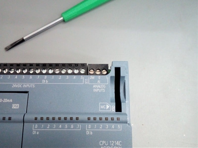
Figure 1. Analog input on a PLC requires the use of floating-point numbers to ensure proper reading of real-world values like temperature, pressure, or light.
The final category appears often when representing real-life values, such as temperatures, speeds, or pressures. These kinds of values are not limited to whole numbers because it’s usually critical to know the value with some precision.
For example, measuring pressure, it might be important to know the change between 15.1 psi and 15.8 psi. If we were limiting the value to whole numbers, they would both appear as 15 psi, losing that precision.
The name of this data type is ‘floating-point decimal’ numbers, often called ‘Float’ or ‘Real’ data types in programming software.
IEEE 754 Structure of a 32-bit Floating Point Number
It’s usually not necessary to understand every mathematical operation involved with converting between an actual real-life value and the binary floating-point equivalent. As is the case with many number conversions, it’s a complicated process and can be researched if needed. But that doesn’t mean that the entire concept should be ignored.
For the sake of this article, these numbers will be called floats. However, you can mentally convert that into real if you are an RSLogix user or any other appropriate title for this term.
A float consists of 32 bits in a PLC. In many modern computer processors, 64 bits may be used, but for almost all PLCs, 32 bits is the standard. This means that in terms of memory capacity, a float does not consume any more space than a 32-bit integer such as a double or DINT. Sometimes, two 32-bit numbers can be combined to form a 64-bit float value.
Parts of a Float
There are three parts of a float, each using a portion of the 32 bits.
Sign Bit
The first bit is the sign bit which identifies whether it’s a positive or negative value. Temperatures can easily be negative, and so can pressure if a vacuum is represented as a gauge value. Speeds might be either positive/negative or differentiated with the use of terms CW/CCW or something like that. The first bit identifies positive or negative.
The following table shows a sample breakdown of a 32-bit float number. This example shows the smallest possible positive value, with an exponent of 1 and a mantissa of 0.
Table 1. Sample Breakdown of a 32-Bit Float Number
| Sign Bit | Exponent | Mantissa |
| 0 | 00000001 | 00000000000000000000000 |
Positive Exponents and Negative Exponents
The second part of a float is the exponent which uses 8 bits. This part of a number is responsible for where the decimal point is actually located since that makes a huge difference in the size of a number. Consider the number 375 - with no decimal place, it’s an integer, a whole number. If we put a decimal point at the beginning, it’s 0.375, but placed differently, it might be 37.5 - the location of the decimal point is very significant.
Exponents can be positive or negative. A positive exponent means the number is larger than 1. A negative exponent means less than 1. In a 32-bit float, the eight exponent bits gives a range of values from 0 to 255. However, both positive and negative values must be possible, so the exponent is actually calculated as follows:
2^(exponent - 127)
The extreme exponent values of 0 and 255 are reserved for 0 and infinity, so for number conversions, we can use 1 up to 254.
Mantissa
The last and largest part of the float using the remaining 23 bits actually shows the numbers that are contained in the value. This is technically called a ‘mantissa’, consisting of the numbers following the decimal point in any float number. The extreme ranges of the mantissa are found by using the binary inverse when all the bits are 0, or when all the bits are 1, which follows:
2 - 2^(0)
and
2 - 2^(-23)
The total range of floating numbers that are seen in a PLC data type table is found by multiplying the mantissa by the exponent. The smallest of both to find the smallest float value. The largest of both to find the largest float value.
2 - 2^0 x 2^(1-127) = 1.1754944*10^-38
and
2 - 2^(-23) x 2^(256-127) = 3.4028235*10^38
Limitations of Float Numbers
Probably the main cautionary consideration of a float number is the additional time to compute solutions, as compared to integer values. In one specific example, according to documentation from Rockwell Automation for a ControlLogix processor, an ADD calculation with a REAL data type takes ~6.5x longer to execute than the same ADD for a DINT.
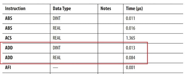
Figure 2. An excerpt from a datasheet comparing the ADD instruction times using a 32-bit DINT versus a 32-bit REAL data type on a ControlLogix or CompactLogix processor from Rockwell Automation.
Sometimes, floating-point numbers are necessary, but this additional time to handle instructions should be a firm reminder to consider using whole number integers whenever reasonable.
Another potential problem for some situations is the inability to truly handle absolutely precise values. For whole numbers, like counting numbers, you can count 100 items, but you never end up with 100.5 items counted. Therefore, it can easily be displayed as 100, there’s no reason to show 100.0000000 items.
However, for values that require a very large precision (which means the mantissa is very large), the value may be rounded. It might not be a problem for many systems, but rounding errors may cause problems when systems regularly must measure large analog values.


perfect