Facebook
 Google
 GitHub
 Linkedin
Connecting Motion to a PLC: A Complete Project
In this article, we’ll connect a Festo CMMT to a Rockwell CompactLogix PLC, and as a bonus, we’ll add an HMI to provide some basic on/off and positional targeting controls.
As with all of our tutorials on Control.com, I’ll start with a disclaimer. There are many, many ways to accomplish motion control. The devices we will use in this tutorial are not the only ones out there. I want to thank Festo for loaning some equipment to explore, connect, and bench-test, and I hope that you can use this guide for your project using a CMMT servo drive and a Rockwell PLC.
In recent articles, we have covered the initial setup of a motion axis and some basic motion commands with the help of the PC-based Festo Automation Suite software. In this article, we will round out the process by controlling the axis from a PLC.
As a bonus, we’ll place a few useful commands on an AutomationDirect series HMI panel to give us simpler access to positions and speeds, avoiding any direct editing of the ladder logic or the tag database.

Figure 1. The project scope includes the drive, physical axis, PLC, and HMI.
Configuring the CMMT for PLC Communication
Previously, we used Ethernet for the configuration alone, and this is done through the X18 port on the front of the device. For PLC communication, we need to use the XF1 IN port on the top side of the drive.
First, we need to switch the drive to allow commands via fieldbus. Open Festo Automation Suite with the previously saved project and double-click on the drive device shown in the window to initialize the plug-in. Go to the “Parameterization” tab and select “Device Settings” (blue oval in Fig. 2 below). At the bottom, beside “Activation via,” select “Fieldbus” from the drop-down.
The “-MP” in the part number indicates this as being a multi-protocol drive; it can be either EtherCAT, PROFINET, or Ethernet/IP. Our example will use a Rockwell PLC, so Ethernet will be our selection. To select Ethernet, expand the fieldbus menu, and select “Configuration” (yellow oval in Fig. 2). “Ethernet/IP - Modbus TCP” will be found in the drop-down menu.
The next step is setting the IP address to the same subnet as your PLC. Select the “Ethernet/IP - Modbus TCP” tab on the left sidebar (red oval in Fig. 2). The fieldbus IP address is set there.
One final step for point-to-point control is to set the telegram structure. This allocates the data packets in the right location so that we can use certain pre-built PLC add-on instructions. Expand profiles, then PROFIdrive, and then select “Telegram” (green oval in Fig. 2). In the Telegram section, choose (111).
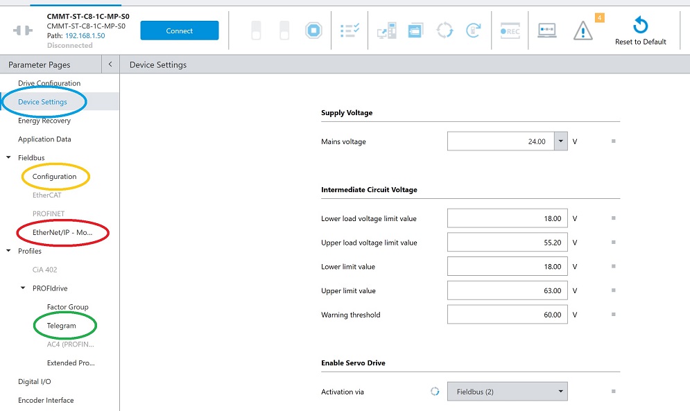
Figure 2. Locations for setting the CMMT to activate via fieldbus.
Save these parameters to the drive and restart. If the PLC isn’t connected to port XF1 IN yet, this is a good time to connect.
Adding the CMMT into Logix
Two installation steps are required for adding the CMMT drive into the Logix software.
First, we add the EDS file. The Festo support portal can be searched by product, so use “CMMT-ST” and navigate to the software tab.
Scroll down to download two items: “Ethernet/IP EDS” and “Function blocks Rockwell.” These will both download a zipped folder, so you need to unzip both.
In RSLogix 5000 (or Studio 5000), use the EDS Hardware Installation tool (blue oval in Fig. 3 below) to select and install the file from the EDS folder.
Next, we need to import the PTP add-on instruction (AOI). On the left sidebar, right-click on “Add-on Instruction” (red oval in Fig. 3) and select “Import AOI.” From our recently downloaded and unzipped folder, select the PTP_Drives_Festo_EIP file. It will add all the appropriate data types.
The very last setup item is to add the CMMT into the project tree, which is done by right-clicking the Ethernet network icon near the bottom left of the controller organizer (green oval in Fig. 3). Add a new module and search for CMMT.
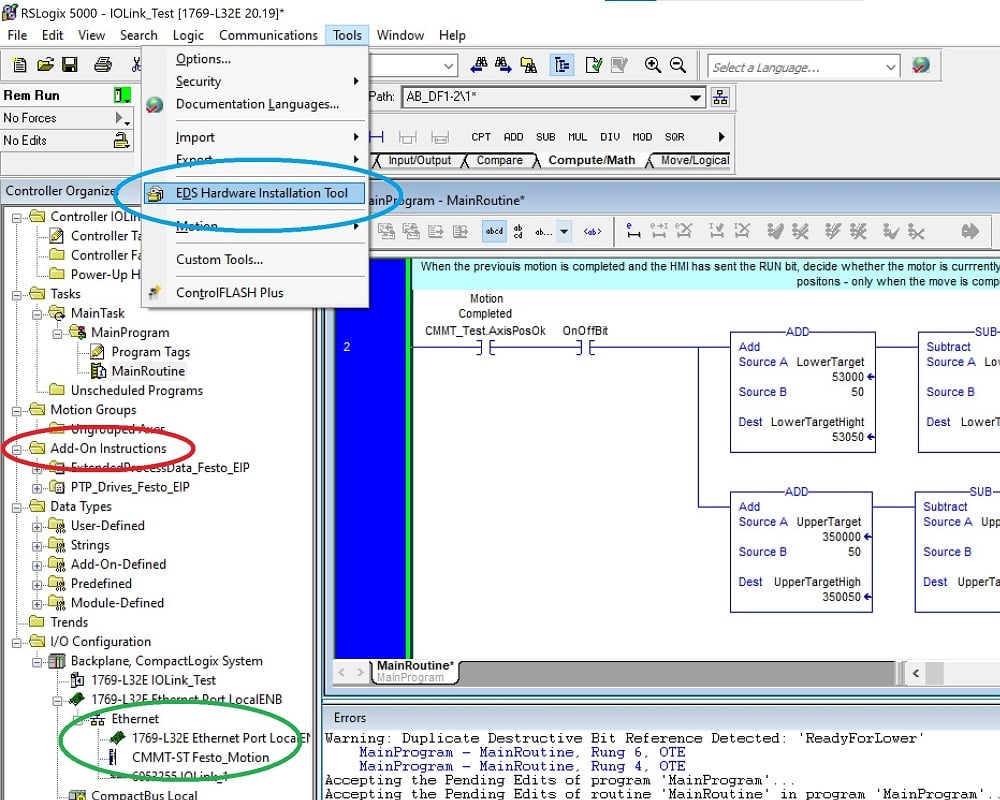
Figure 3. Installing the EDS and inserting the AOI into the project.
Provide a module name (this is important in the next section) and the IP address, but you will also need to click “Change” in the module definition and select the right data types and numbers, as shown below.
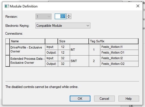
Figure 4. Data types and sizes for the module definition.
Programming
Until now, everything has been setup; now it’s time to actually drive the axis!
In the main routine, create a new run and drop in one of the new PTP AOI commands. This function block has a long list of status outputs and input parameters to be linked to tags. In the name field at the top, PTP_Drives_Festo_EIP, assign a name for this axis, right-click, and create this as a new tag. It will be placed in the program scope tags folder.
We also need to connect the input, output, and connection areas to the tags that were created when we defined the module. Remember the module name from the previous section? Use that name to assign the following tag areas:
DRV_Status = Module_Name:I1.Data
DRV_Control = Module_Name:O1.Data
ConnectionFaulted = Module_Name:I1.ConnectionFaulted
Download this program to the controller. First, check to make sure the I/O OK is solid and communication with the CMMT. Next, look at the function block on the rung; the Error and Lockout output bits should be off (if they are on, go back and verify that the CMMT is set to activation via fieldbus).
If all is well, first, set the ModePos to 4 (homing mode), the AxisEnable to 1, and the ExecuteMode to 1. This will home the axis and enable positional commands.
Now, change the ModePos back to 2 (for absolute positions; 1 would be incremental moves). Set a Velocity, something moderate like 30-40 mm/s as a test. If the homing procedure completed successfully, look at your axis and assign a Position. This value is scaled to thousandths of mm (μm), so a target position of 150 mm would be 150000 in the tag.
Once the velocity and position are in place, toggle the ExecuteMode bit to 0, then 1 for a rising edge trigger. Explore various velocities and positions, and re-execute to run the program.
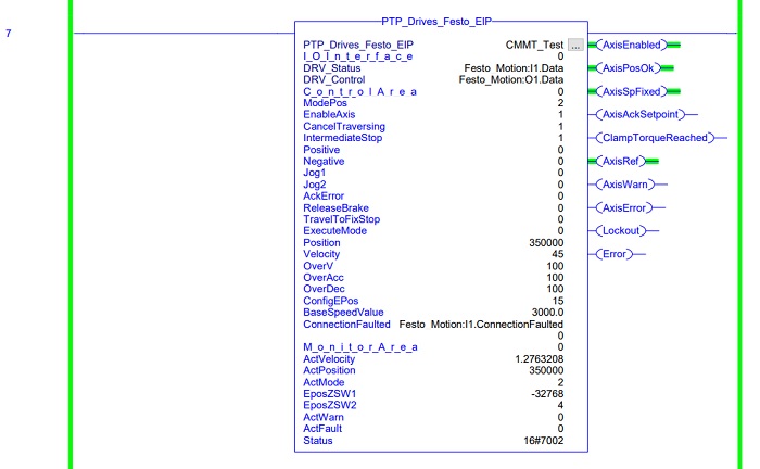
Figure 5. The add-on instruction for point-to-point commands.
Designing a Motion Program
Our last exercise is purely optional, but we’ll design some extra tags and an HMI interface for control. The overall goal of the ladder program is to cycle motion back and forth, just like the record set in the previous article. The difference is that now I want to control the velocity and the stopping positions as the axis drives to and from the motor end.
This is simply one way to create this task, but there are many, many more. I’ll provide my example code. If you don’t have an HMI, you can use the same program but simply toggle the bits in the controller tags or connect them to physical digital and analog inputs.
For this demo, I created five tags that will interact with the HMI (or real-world I/O):
- AxisEnableBit (BOOL: powers up the axis, but does not drive the motor)
- OnOffBit (BOOL: activates the sending of motion commands)
- Velocity (DINT: speed in mm/s)
- LowerTarget (DINT: abs position in μm, target for the stopping position near the motor)
- UpperTarget (DINT: abs position in μm, target for the stopping position away from the motor)
In my own project, I used a C-More EA9 HMI from AutomationDirect, but you can use any screen compatible with RSLogix/Studio 5000. Link each of the BOOL tags to buttons, and each of the DINT tags to slider bars.
Festo_CCMT_PLC_MainRoutine.pdf
Festo_CCMT_PLC_MainRoutineTags.pdf
Check out the project, and be sure to share any improvements or upgrades you make by leaving a comment! Happy programming.