Troubleshooting PLCs: Recognizing Visual Status Indicators and LEDs
Machine downtime can be very stressful for everybody involved. Next time you face a challenging system failure, try some of these LED troubleshooting techniques to reduce stress.
When automated equipment breaks down, the world stops spinning.
At least, that’s how some people interpret the situation.
In reality, manufacturing equipment is designed for the sole purpose of making money for the company. When that equipment is not working, the company is losing money with every excruciating minute of downtime. Understanding the various status LEDs that are built into the front of virtually all PLCs, I/O modules, and communication modules can help troubleshoot issues without having to open the programming software or even get a laptop.
Status LEDs to Light Your Path
Nearly every automation device has at least one status LED, more if it has communication or I/O technology built in. These LEDs can be used to get an instant cue as to the current status of the device.
Common color codes are often used to help diagnose in an instant, most often something like red to indicate bad or failure and green for good.
Bi-color and multi-color LEDs are often used with small devices that do not have much room for more than one LED. They are also used to give many different statues at one time.

Figure 1. PLC with front-facing display. Image used courtesy of Siemens
The Marque And Display Screens
For many of the latest generation controllers, there is often a marque that can display messages that provide very descriptive troubleshooting hints directly on the device.
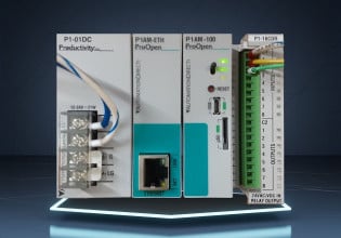
The latest revs of the Allen Bradley CompactLogix and ControlLogix families of PLCs have a small marque that displays the PLC name, the program running on the PLC, and the status and IP address of each Ethernet port. If a mapped Ethernet module stops responding the marque will display an I/O fault. The Productivity PLC series from Automation Direct provides a similar multi-line LCD text screen for diagnostic information.
Some newer PLCs have integrated full-color LCD displays and keypads so that maintenance staff and integrators can scroll through very descriptive fault and warning messages and configure some settings. The Siemens S7-1500 PLC series offers this type of display and keypad right on the front of the CPU module.
PLC Status LEDs (On the CPU)
Most PLCs nowadays have built-in communications with a separate set of LEDs just for the communications. So when troubleshooting a PLC issue, you must first determine if you have a communication problem or a PLC problem.
Power LED
If none of the lights are on, chances are there is no power to the device, check for voltage at the appropriate connector. For some PLCs, there is a power LED that illuminates green if there is sufficient power. Power can be provided both for the CPU as well as field power for the I/O device. There may be separate power indicator LEDs for these two systems.
Typically, a power-on sequence will flash one or more LEDs on the CPU and even the I/O modules. This lets you know that the system is booting, but if the PLC doesn’t come out of this booting stage, you might have a corrupt program or a defective processor (jokingly called a bricked unit).

Figure 2. Status indicators on the front of the PLC CPU. Image used courtesy of the author
With most PLCs, the power LED will flash or alternate between green and some other color (red and yellow are the most common) during the booting stage. This same flash sequence will be seen during a firmware upgrade where the PLC must be restarted multiple times.
Status / Error LED
Most PLCs include an LED to signify the presence of errors or if the processor is otherwise operating abnormally. Some manufacturers call it the S/E LED or the Error LED, but either way, a solid or flashing red error LED points to something wrong with the PLC or a problem with the installed program.
In the case of the B&R X20 PLC, the S/E LED will flash between green and red, and the sequence of the flash will help determine the cause of the error. For example, if the S/E LED is red for a long pulse followed by two short pulses and another long pulse, with a two-second pause in between, a hardware error is reported. If your PLC follows such a code pattern, you will certainly need to consult the documentation to interpret these error or fault status indicators.
Run / Stop LED
Most standard PLCs have run/stop LEDs to indicate the actual current mode of the program execution. If the PLC has been commanded to stop because a user is downloading a program, the stop LED will light up in red, yellow, or even green. Once the PLC has been put back into run mode the PLCs run LED lights up again.
Forced I/O LED
With some PLC manufacturers, there is a possibility of forcing outputs (and sometimes even inputs) to be on or off. This is very useful during the phase of testing for integration, but it can be extremely dangerous if the equipment is already in production. Sometimes there is an LED that shows the status of the I/O forces, if they are enabled, you will want to go into the program and disable them as soon as possible.

Figure 3. I/O indicators can be seen on the front of both local and remote I/o modules. Image used courtesy of the author
I/O Status LEDs (On the Modules)
Most inputs and outputs will have at least one indicator per channel to show the status of that port. Discrete (digital) modules will simply illuminate or not, depending on the port status. Analog terminals are a bit trickier, and any LED indicator will only present power information, not the actual value of the analog signal.
Local Discrete I/O Points
For input modules, the LED will light up when an input is detected, and for outputs, the LED will light up when the output is turned through the program, even if nothing is connected to the output.
If the input LEDs respond properly, but the output LEDs never update, the PLC may be in ‘stop’ mode. If the output LEDs respond properly, but the actual output devices do not energize, turn your attention to examining the output wiring to identify the problem.
Safety I/O Modules
If you are using safety-rated modules, there will be some internal checking for proper configuration and wiring to test points. If test points are being used, the proper test point needs to be wired to the correct input channel. If something is incorrect, the output or input channel LED will be red.
Once again, some manufacturers will flash the red LED in different sequences to help diagnose the problem without programming software.
Remote I/O Modules
With remote or expandable I/O modules, there is often an LED indicating the bus communication status. If a module is added to the backplane without updating the configuration, the whole I/O module will become unresponsive and the bus indicator LED will change color. The same event will occur when a module is removed without proper configuration adjustment.

Figure 4. Com ports use link and Tx/Rx indicators to provide a network traffic status. Image used courtesy of the author
Communication Modules
Many devices have communication modules embedded in the CPU, typically with a separate set of status LEDs just for communication. There are two LEDs per communication port, one for link status and speed, and one for packets transmitted or received (Tx/Rx). When the device is plugged into a network, the link light should be solid green or yellow. The Rx/Tx LED flashes rapidly as packets are transmitted and received.
With Ethernet communications, the device needs an IP address before it can begin transmitting or receiving data packets. When a new device is plugged into a network, the link light might be green or yellow with the Rx/Tx light remaining off until an IP address is set.
Industrial devices will sometimes have a feature for locating them physically by using the status LEDs. When triggered, both the link and Rx/Tx LEDs will flash at a constant frequency.
If the link LED is solid, but there is no activity after you have set your IP address, confirm that the IP address is in the subnet range of all other devices and that there are no firewalls or VLANs preventing communication.


