Facebook
 Google
 GitHub
 Linkedin
Safety Devices - The When, How, and Why
Machine safety design can be a daunting task with all the different safety devices on the market today. Choosing the correct device for your design can be made easier by understanding when to use the proper device.
Machine Safety
Automated equipment can be a simple pneumatic cylinder or an assembly of different automation components all working together. No matter how complex the system is, safety for the operator, integrator, or maintenance staff needs to be considered. Safety systems can be very simple or very complex, depending on the system they are installed in. Typically, the more complex the automated system, the more complex the safety system will be. There are many different safety devices on the market, and it can be overwhelming to decide which device to use and when. Below I will outline the when, how, and why for common safety devices.
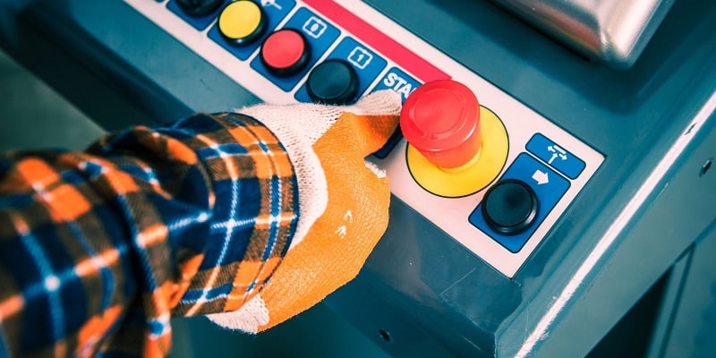
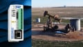
Figure 1. Safety devices are found in every manufacturing setting, regardless of industry. Image used courtesy of Canva
A Note On Standards and Safety Integrity Level (SIL)
With automated equipment being around for so long, there is no shortage of documentation on guidelines, best practices, and standard design principles for safety systems. These documents provide a great resource when designing safety systems and should be consulted to ensure you are providing safe equipment.
SIL is a measure of the failure rate of a device expressed in terms of the probability of failure. Typically, if a device is considered safety-rated, there will be a published SIL number. This number is not a rating but more of a guideline as to what kind of system it can be used with. If your system requires a SIL rating of 3, then all the devices used within the safety system must have a SIL number of 3. There are four SIL levels with 4 being the highest level, meaning the lowest probability of failure.
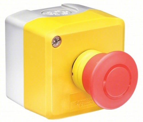
Figure 2. Emergency stop (e-stop) button. Image courtesy of Schneider Electric
Emergency Stop Button (E-Stop)
The e-stop is likely the most common safety device, and it is typically the first safety device added to a system. An e-stop push button typically has two normally closed contacts and one normally open contact for monitoring and is colored bright red with a yellow label. The purpose of the e-stop is to stop and de-energize all sources of motion or hazards within the system. For pneumatics, stored pressure will be vented to the atmosphere and STO signals will be off for any motion devices.
There are a few different ways to make use of an e-stop button, and one common way is with a safety relay. The safety relay will have two monitor circuits which pass through the dual contacts on the e-stop button. When the button is pressed, the contacts will open. This causes a break in the redundant safety circuits, triggering the safety relay to open its contacts.
Another way to monitor the state of the push button is with a safety PLC or safety controller using special safety inputs. The PLC will need to be programmed to open output contacts when the push button is pressed. If the system is very simple you might see the control voltage for contactors or STO signals passed through the e-stop contacts.
An e-stop button is a very inexpensive way to easily stop and de-energize any hazards within a system. They can be integrated into very simple or complex safety systems without much hassle. If it is determined that your system contains hazards or poses a safety risk to operators, then an e-stop should be implemented.
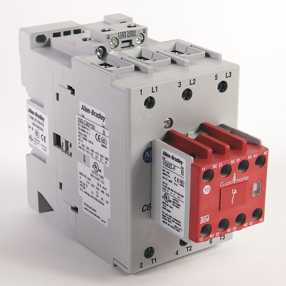
Figure 3. Safety contactor. Image used courtesy of Rockwell Automation
Safety Contactor
A safety contactor is similar to a standard contactor where a control voltage causes contacts to open or close—the difference with safety contactors is the contacts will be forced guided or fail-safe with an allowable SIL number.
Commonly, safety contactors will be used to break any circuit that provides power to devices that are hazardous or cause a safety risk. When used with a safety PLC, the outputs will open or close contactors based on the logic within the PLC. When somebody opens guard door contractors that provide power to valve banks or servo drives, it will open, forcing the valve banks to vent line pressure to the atmosphere and triggering servo drives to stop.
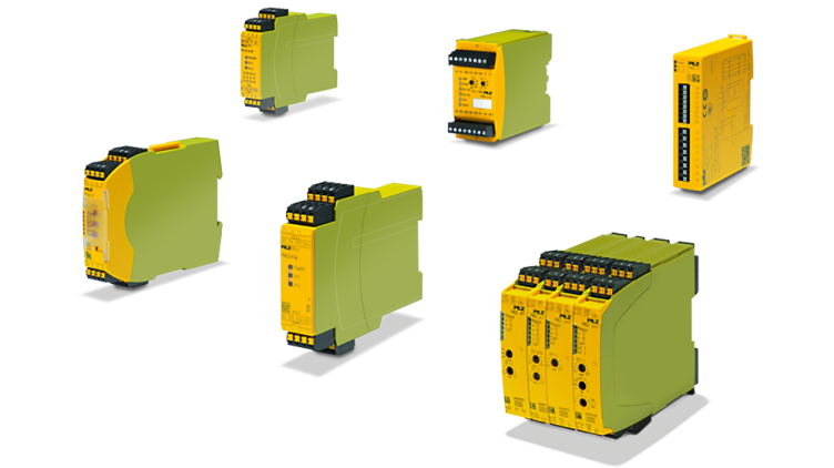
Figure 4. Safety relays. Image used courtesy of Pilz
Safety Relay
A safety relay is similar to a typical relay only a safety relay will have internal logic and error checking. Along with contacts, the safety relay will typically also have a dual-channel monitor circuit which determines if the system is safe. The safety relay may also have a reset input to allow a controllable reset.
If you have determined that your system will require safety inputs, such as a light curtain, e-stop button, or palm buttons to control the equipment then a safety relay will be required to monitor those safety devices and to safely stop the hazardous devices.
The monitor circuit on a safety relay needs to be complete in order for the system to be determined as safe. This requires the monitor circuit to be wired through the normally closed contacts on each input device. Some safety relays will have dual monitor circuits, and both of those circuits will need to close and open with a very short time difference.
A safety relay has internal logic that ensures the dual monitor circuits are separate and they function together. This internal logic can also detect faults within the safety devices themselves. If one of the dual contacts is not functioning, that would cause a fault resulting in opening the safety contacts.
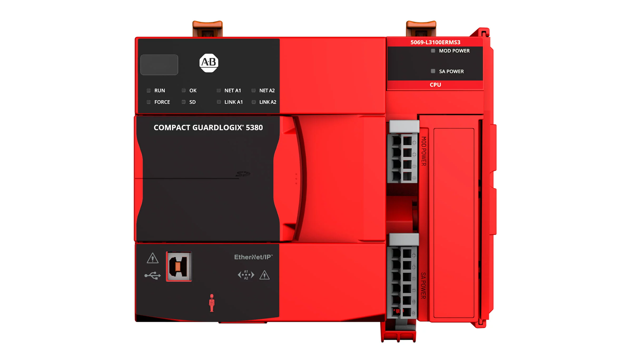
Figure 5. Rockwell (Allen-Bradley) Compact GuardLogix 5380. Image used courtesy of Rockwell Automation
Safety PLC / Safety Controller
A safety PLC uses safe inputs and allows a user to develop safety programs that set safety outputs at appropriate times. When a safety system becomes complicated or requires multiple safety relays, it is best to use a safety PLC. Each of the safety inputs has the same if not more error checking and diagnostic as a safety relay, and the outputs will sometimes have a similar error checking.
Some safety PLCs will use function block diagrams to develop simple logic cases to set or reset outputs, and some PLCs will use standard ladder logic and special function blocks to handle the inputs and outputs. Variables within a safety program are considered safe, if non-safe variables are required they will need to be mapped.
Safety PLCs are becoming more affordable and are very flexible. The I/O can be expanded and a variety of safety input devices and output devices can be used with a safety PLC.
Combining All The Devices
As you can see, all of these devices are designed to work together to form a safe network that ensures hazards are disabled before people enter or use the equipment. Safety systems can be designed to be very flexible or rigid, depending on the devices chosen. When designing your safety system, remember to allow for flexibility within your system in case your safety needs expand in the future.