Facebook
 Google
 GitHub
 Linkedin
Understanding and Using Safe Torque Off (STO) for Motion Systems
Safety is one of the most critical aspects of machine design. Today, with network connections between different machines and control centers, safety signals must be shared logically and reliably across networks.
Any system involving the motion of tooling or components using motors includes inherent possible hazards, but there are systems in place to reduce these dangers. Just about every motion control device includes a concept known as safe torque off (STO), a digital signal included in order to operate the motor.
If the STO signal is enabled, torque will no longer be applied to the motor. The STO function ensures that the motor and environment is safe for performing maintenance or for entering an area that contains a motor. The STO function is also referenced in IEC 60204-1 “Safety of Machinery - Electrical Equipment of Machines”. The standard references an STO function as one of the ways to prevent unexpected startups.

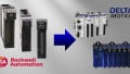
Figure 1. Rockwell Automation’s Kinetix servo driver series is one example of a system containing safe torque off (STO) signals. Image used courtesy of Rockwell
What is STO?
A safe torque off (STO) signal is typically a 24 V signal that comes from a control system like a PLC or safety relay. It can be a single or dual signal that needs to change state together with a small amount of error in timing. The signal tells the motor drive that the system is safe to operate. If the signal goes low at any time (0 V), then the drive will stop providing power to the motor which means the motor will no longer be able to apply torque. Any 24 volt power supply will satisfy the STO requirement, but in order for the system to be deemed safe by third-party safety inspections, the signal will need to be passed through the contact of a safety device or come from a safety-rated output of a safety PLC or safety relay.

Figure 2. Logical block diagram of a servo control signal alongside an STO signal for motor operation. Image used courtesy of Advanced Motion Controls
How Does STO Work?
The STO works just like the signal from a common button or switch. When the switch is open, the power from the drive going to the motor is physically removed or opened. Removing the power doesn’t abruptly stop the motor but allows the motor to coast without torque. Depending on the friction and inertia of the system, the deceleration time for the motor could vary.
Some systems monitor the STO signal and enable a break when the signal goes low. The STO does not actually remove or switch the incoming power to the drive by itself, in the same manner that a motor overload might. If the drive’s electrical components need to be serviced, then the main electrical service would still need to be shut off (and locked out) before working on the drive.
Because the STO signal causes the motor to free spin without torque, it is common to add a delay in the safety program before enabling the STO function. This delay is used to issue a stop to the motor and allow the motor to come to a stop. The delay is typically less than one second, which is more than enough time for most motors to come to a complete stop.

Figure 3. Servo motor from the Siemens SIMOTICS S line. Image used courtesy of Siemens
How do Safety Devices work with STO Signals?
There are a few different ways to generate a “safe” signal—the simplest way is to use a safety relay. The relay will have a monitor chain that will determine if all E-Stop buttons are not pressed and that all guard doors are closed by passing a signal through the normally closed contacts of all devices. When the signal from the monitor out reaches the monitor in, the monitoring chain is satisfied and the reset button can be pushed, causing the safety contacts to close. This allows voltage to pass through the safety relay and into the drive systems signaling the STO signal. Standard wiring practices can be used when wiring an STO signal in this fashion.
How Does a Safety PLC and Safety Relay use STO?
A safety PLC uses standard ladder logic or function block diagrams to create safety programs that monitor safety-rated inputs and set safety-rated outputs. The inputs can be used to generate conditions to turn on different outputs at different times. The code in the safety program uses special function blocks to compare dual inputs to ensure they switch at the same time.
The programmer will need to determine the safe condition of the motion devices. Then, once these conditions are met, the STO signal can be sent directly from the safe output card or energize a safety contactor that will pass voltage to the STO ports on the required drives. The same wiring practices can be utilized as with the safety relay option. The advantage of using a safety PLC is the flexibility in the I/O and error diagnostics on the connected devices.

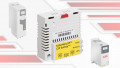
Figure 4. Rockwell Automation’s Guardmaster safety relays serve as a link between end safety devices and controller networks. Image used courtesy of Rockwell
How do Industrial Safety Protocols use STO?
More servo drives are being controlled these days via industrial protocols such as CIP safety or ProfiSafe. These protocols support safety signals to be sent over Ethernet infrastructure, thus eliminating the need for additional safety I/O cards. A safety PLC is required to use this technology. Once the drive is added to the Ethernet device mapping, special function blocks can be used to set the STO signals when conditions are safe.

Figure 5. Visual explanation of safety and STO signals that can be safely transported using common industrial protocols. Image used courtesy of ODVA
Devices That Typically Use STO Function
Most modern motor-driven motion devices use STO signals. These devices include servo motors, stepper motors, VFD-driven motors, robots, and linear conveyance systems.
Other motion devices might use a similar signal to ensure that the system is in a safe state before applying power, but some of the more proprietary systems might use a different term than STO. Rockwell and Siemens both use a protocol version of the STO function on their servo drives.
With more devices being controlled over industrial protocol, we can certainly assume it won’t be long before most safety signals are transmitted over more standardized industrial protocols.
Featured image used courtesy of Fuji Electric
Interested in more motion control content?