Facebook
 Google
 GitHub
 Linkedin
Using PID and Feedback Loops for Precise Motion Systems
PID controllers are an excellent method of using feedback to turn an otherwise open-loop system into one which can follow a carefully prescribed profile, correcting for inconsistencies caused by the equipment, the environment, and even the products in the manufacturing process.
In many systems, it is sufficient to send voltage to a motor or valve, and expect it to perform properly. But for other systems, it’s critical to know an exact RPM or position, and if the system isn’t performing exactly as intended, it must be corrected. For these systems, we turn to closed-loop PID systems.
In some industries, it is critical to have certain motions controlled and calculated very carefully, or the results could be disastrous. Most of the time, as long as motors drive as commanded, and solenoid valves open and close as required, the system works just fine. But in those critical moments, an error of mere fractions of an inch can destroy equipment and injure people.
In those types of systems, we turn to some sort of sensor to report back information about how well the motion device is performing its task. This sensor information is called ‘feedback’, and when it’s added into a system, the added benefits can be pretty amazing.
This precision motion control cannot simply be called motor control since it’s common for the motion to be in the form of hydraulic cylinders and sometimes even air. Motors are a classic example of motion, but these feedback loop motion systems can be driven regardless of the source of the motion.

Delta Computer Systems’ RMC75, an example of a PID controller with expanded I/O capabilities. Image used courtesy of Delta Motion.
Before investigating motion control system, it should be noted that one type of motor, the Servo Motor, does fit into this category. However, the entire control system is contained within the servo driver board, and usually can’t be individually controlled and tuned in the same manner as a motion control system. We’ll be focusing on motor and hydraulic control for the scope of this discussion.
Sources of Feedback in PID Systems
The choice of sensor used to obtain feedback really depends on what kind of motion is intended from the system. For a hydraulic cylinder, the goal is pretty obviously linear motion with precise speeds and stopping locations. For motors, it might be a bit more complicated since RPM might be the goal, or perhaps it’s still linear motion through the use of a toothed belt drive or ball screw, commonly seen on a CNC machine axis.

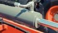
A linear position sensor made by Temposonic and used to locate the precise location of the shaft of a hydraulic cylinder. Image used courtesy of MTS Sensors.
For those hydraulic cylinders, the sensor must return back the precise position of the end of the cylinder. Usually, it must be precise down to fractions of an inch or millimeter. Most commonly, the center of the cylinder is hollow, giving room for a long sensing rod that works on principles of magnetic fields - often field disturbance or Hall Effect sensing. Sometimes these are named by brand, including Temposonic, a common choice for hydraulic applications.
With motor drive systems, the encoder is almost always the choice to retrieve information about RPM. For continuous motion, the rotational speed is the end target parameter. For linear electric motion, an encoder can still be used but magnetic tape position sensors or even linear potentiometers can be employed. Although the latter usually only for very small ranges of precise motion.
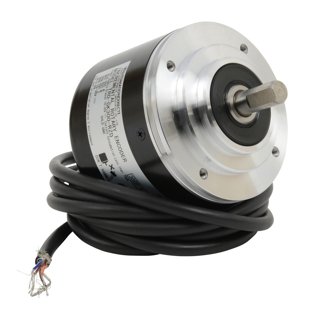
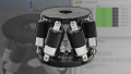
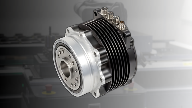
A rotary encoder for heavy-duty applications. Image used courtesy of Automation Direct.
Comparing the Current Value to the Target Value
No matter whether the goal is to achieve a particular position or a particular speed, we refer to that value as the ‘target’ or sometimes ‘set point’.
It’s important to remember, however, that our entire task is not simply to get from a starting point to a target point as fast as possible. If we turned on a motor with infinite acceleration, not only is that impossible, it would consume a lot of current. Rather, we want to get to our set point at a particular rate. This means that we are rather interested in an entire “Target Profile”.
We should stick to using that term to discuss our end goal, and exactly what velocities and accelerations we should use along the way to achieve that entire profile, and not get too focused on the end set point at the exclusion of everything else.
With the proper sensors in place, all that is required is to obtain a reading of the current value as fast as reasonable. This could be a reading of the exact position of the cylinder in inches. Or for motion, it could be the exact number of counts delivered by a rotary encoder. Three critical properties are then calculated.
First, the current position or RPM is compared to the target set point. If the system still needs to move to get the target, it tried to do so.
Next, the previous two readings are subtracted and divided by the time between readings giving the current velocity. This also is compared to the target profile (remember, not just the end location is important, but also the speed to get there).
Finally, the two previous velocities are subtracted and divided by the time between them, giving an acceleration.
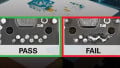
Each time a reading is obtained, the current value is compared with the target set point, and the difference (again, subtraction) between them is called the ‘error’.

A typical ‘block diagram’ representing the loop from output voltage, back through a feedback loop, and compared to the set point to determine the error.
Defining the PID Terms
For this article, the PID terms will be defined briefly, giving only a broad overview of the effect they play in a closed-loop control system.
P. Proportional is based directly on the error, which again is the difference between the current value and the target value. If the error is large, more voltage will be sent to the motor or hydraulic valve. If the error is negative, that means the value has shot beyond the target and must be brought back in the other direction. This is the most simple of the control parameters.
I. Integral is a total sum of all the error readings taken over a longer period of time. If you add up the error values and find that they are increasing at a constant rate, it means you are adding the same exact error with each new reading. This would show that you are still some distance away from the target, but not moving, the error stays the same.
Therefore, the voltage to the motor should be increased. This parameter is helpful if you are close to the target, but need a boost of power to make it all the way.
D. Derivative is a calculation of the speed (or rate) at which you are going towards the target value. If you appear to be getting there more slowly than desired, boost the output voltage. If you are approaching too quickly, lower the voltage.
As you can tell from the descriptions, each of these parameters can have some conflict with the others. While one is trying to boost the motor voltage, another may be attempting to restrict the voltage.
The art of finding the right balance of P, I, and D correction factors is a process known as tuning. Tuning is most commonly a software-driven process, made easier by controllers with proprietary software, many of which can add in additional features that can drive the systems even more efficiently than just with these three parameters alone.
Interested in learning more about PID controls and gain?
Articles:
- What is Proportional Gain?
- An Overview of Integral Gain
- Integral Windup Method in PID Control
- Motion Control Systems: Velocity and Acceleration Feedforward
- Proportional Gain and Proportional Band Explained
Textbook: