Facebook
 Google
 GitHub
 Linkedin
Joystick Controls: How Do You Use Them For Automated Systems?
We usually think of joysticks in terms of video game controllers, but they exist in all kinds of industrial systems: heavy equipment, overhead cranes, and even some robotic controls. But how do they work?
Everyone has seen the controls inside of a big excavator or tractor, and there are joysticks to control the functions of motion. You move a lever arm and an action occurs, maybe a gantry crane slides to the side or a bucket extends, but these small controls can run some pretty big devices.
What Is a Joystick?
The main concept of a joystick is really just a combination of levers that move in two directions. We usually call them the X and Y axes of the joystick. Sometimes they are variable, so the more you move the joystick, the faster the response time, but they can also be simple on/off controls.
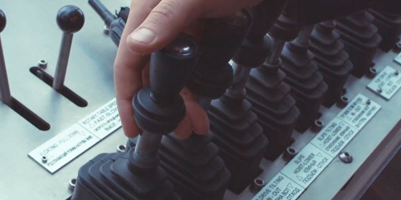
Figure 1. Joysticks can be electrical or hydraulic, and they are found everywhere throughout the automation industry. Image used courtesy of Canva
We find them all the time on the controllers of video games and RC cars, but the ones used in industry are often quite different.
There are actually a few different kinds of joystick controls, even though all the lever arms may look the same from the outside. We’ll take a closer look at the three most common types of joystick controls that can be found in automation systems.
Hydraulic Control Valves
For most heavy machinery, the lever arm is directly connected to a valve in the hydraulic system line. This variable valve is actually a combination of four different spool valves, placed at the top, bottom, left, and right of the valve body. Each set of opposing valves is connected to the extend and retract of a cylinder or actuator so that if you move the stick up, a cylinder will extend, and when you pull it down, that same cylinder retracts. This isn’t always the arrangement, but in most situations, they are paired like this.

Figure 2. Hydraulic valve with inlet port and four spool-controlled outlet valves. Image used courtesy of Summit Hydraulics
The base of the lever contains a swash plate, a metal disk that sits level when you let go of the handle. As you move the handle around, the angle of the plate changes and begins to press down on the spring-loaded spools. Diagonal movements of the handle can press two valves simultaneously, but you can’t ever press three valves at once. The swash plate arrangement is very common for all kinds of variable hydraulic flow controls.
These spool valves are usually variable so that as the pushing force on the lever is increased, the valve opens further, and more fluid flows, so the resulting action is faster. This allows equipment operators to control very large equipment with great precision, and those with experience can manipulate them with impressive skill.
Variable Electrical (Potentiometer) Joystick
As manipulative control for robotics and automation advances deep into the 21st century, it’s common to find designers relying on controls that are familiar to the workforce generation. Many (if not most) technicians have played video games at some point, and the concept of a joystick is nothing new at all.
These joysticks usually work in two axes, each with a (+) and (-) direction, just like the hydraulic controls previously described. However, the electrical signal comes from a carefully constructed set of potentiometers attached to each side.
These rotational devices measure the current position of a wiper arm as it rotates around a pivot point, raising and lowering the voltage. This is a very simple form of control, but it does require analog voltage inputs for the controller I/O, so some industrial controllers may opt for a simpler digital design.

Figure 3. A variable electrical joystick has two axes, each with a potentiometer designed to move through its entire resistance range with only a few degrees of motion.
The factor that makes these potentiometers unique and ‘carefully constructed’ is that a joystick usually only pivots about 30° or so, about 15° in either direction, with a spring returning it to the center. Normal potentiometers have a rotation span of nearly 360°, so the pots used in joysticks must travel through their entire resistance range within that 30° span.
Discrete Electrical Switch Joystick
Although this is the final category, it’s definitely not the least common for industrial applications. For many industrial controllers, it is preferred to use a simple, discrete on/off control which is reliable, nearly immune to noise, and easy to troubleshoot for failures. If the process doesn’t require a fine, delicate range of motion, the on/off joystick is perfectly sufficient.
There are 2-position and 4-position joysticks. The 4-position version is the equivalent of the 2-axis joysticks described above. You can usually move these diagonally to contact two electrical positions at once, so they can sometimes be described as ‘8-position’ or ‘8-way’ but they still only contain four sets of contacts.

Figure 4. A 4-position joystick with N.O. screw terminals in the base. Image used courtesy of AutomationDirect
For the 4-position versions, a push in any direction engages a set of N.O. contacts which would likely be connected to a PLC or I/O block.
The bases for these switches often resemble typical pushbutton and quarter-turn devices, but there is something unique about having four positions.
Most industrial switches can have two contact blocks screwed or clipped to the bottom, with others possibly stacked onto those first two. Normal pushbuttons will press down on both of those contact blocks at the same time. Quarter-turn switches engage only one or the other. So for these devices, the typical two-contact arrangement works great.
However, for the 4-position joystick, it is not sufficient to only have two contact blocks below, so most of these devices require special contact blocks with four different spring-loaded detent plungers, each one pressing down on one of the four contact sets.
In standard industrial fashion, each contact set contains two terminals, so most 4-position joysticks will be wired with eight terminals. Some screw terminals are exposed right on the bottom of the joystick itself, while some others make use of an 8-pos M12 quick-connect fitting to ensure a more reliable (and compact) wiring experience in rough conditions.

Figure 5. 4-position joystick with an 8-pos M12 connector on the bottom. Image used courtesy of AutomationDirect
Joysticks in Industrial Automation
These control devices can definitely increase productivity in many situations where an operator needs careful control over a manual system. As you can imagine, they must be built more ruggedly than many other controls, as they are likely to be handled roughly in harsher environments.
Understanding the control types, both operator and contact block set, can help to quickly choose the right device for a system, or to troubleshoot and repair one if it has gone bad.
Related Content