 Facebook
 Google
 GitHub
 Linkedin
An Introduction to Synchronized Motion Control
Learn about what synchronized motion control is, including its different types and applications.
The human body is a marvel. Consider the various factors involved in the simple act of walking. We see the ground before us and the objects through our eyes. Assume there is a box before us. We must decide whether to walk around the box or to step on the box. If there is no alternative way, we must step on the box to cross. Our brain should judge whether the box can handle our weight. Then we place our left foot in front of our right to move forward.
The act of walking, which we perceive as a simple or mundane task, has a lot of information handling happening in the background. Many organs and moving parts are involved in executing the task. It is evident from the viral video New York Subway Stairs where a fraction of an inch misalignment in the height of stairs from a New York subway station causes commuters to trip. A minor deviation from the ‘all steps are of same height’ assumption in our walking algorithm throws a wrench in the whole process.
In robotics and automation, processes in sync can gain significant advantages in precision, accuracy, efficiency, time, and cost. Industrial robots are widely used in a variety of industries, including automobile manufacturing. In Ford’s assembly line, each station did only one focused task. With modern robotics solutions, one station at the assembly line can handle multiple processes enabled by synchronous motion.
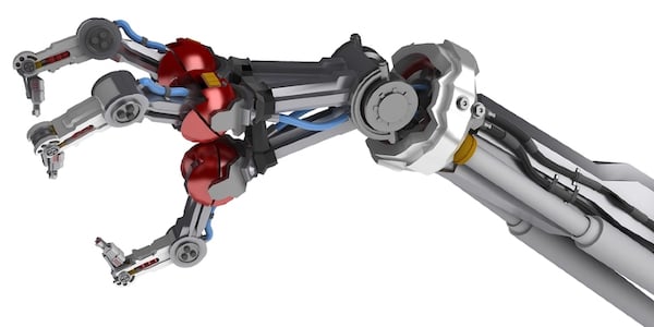
Figure 1. Robotics and automation use and benefit from synchronous motion.
Synchronized Motion
We can walk properly because multiple organs (devices) collect information, transmit the information through the nervous system, process information, and other organs take action.
In the video by Valk Welding below, two robotic arms are welding different parts of an object simultaneously. At the same time, the surface to be welded is turned with a contraption to give the robotic welding arms easy access.
The welding arm needs to know when the turning contraption has completed its task. It also has to know the coordinate axes where the next weld is to be done, moves to that location, and weld according to the specifications for the spot. Both the welding arms work in parallel at different locations.
Once the welding is complete, the turning contraption has to know the task is done to shift to the next position. The whole system will have a program and routine to be followed for each new object to be welded. The various parts in this station need to ‘talk to each other’ to complete the tasks. Modern network protocols enable this communication.
Synchronized Motion Control and Types
Collecting and processing data to monitor and control components and enable synchronized motion is performed by synchronized motion control. Synchronized motion control can be achieved with a combination of motors, oscillators, actuators, MCUs, PLCs, network technologies (like EtherCAT), and software tools. There is a broad range of applications for synchronized motion and the control used for each will differ.
Synchronized motion control is mostly used when there is a need for synchronous motion in a three-dimensional space. Motion in different axes (x, y, z) is executed by different motors. The control for such a system can be done by a single-axis controller or multi-axis controller.
As the name suggests, a single-axis controller can control only the motor for one axis and a multi-axis controller can control motors of multiple axes from one controller. How motion control is designed can have a wide range of possibilities. By clustering some common attributes, synchronized motion control can be divided into some broad classifications.
Simple Motion Control Synchronization
As the name implies, this is the simplest form of achievable motion control. Here, the motors in different axes are synchronized by an external trigger. Change in synchronization state is also triggered by the external signal.
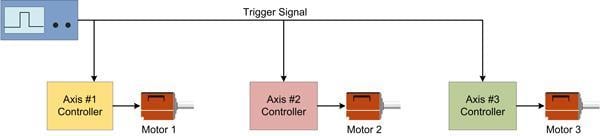
Figure 2. Schematic of simple motion control synchronization
This simple control scheme can be used in conjunction with PLCs, ICs, and other controllers to create automatic trigger conditions (or breakpoints). Different logic can be generated to perform different sequences of actions according to various environment variables provided as signals from sensors.
Master-Slave Synchronized Motion Control
In cases where there is a need for synchronization not just at the start of the process but at different intervals, a simple system is not sufficient. There needs to be synchronization between different axes.
Another case where simple control does not work occurs when the motors run for so long, they drift out of synchronization when single-axis controllers are used. Controller clocks are run by the signals generated by the internal oscillators. All the controllers will not produce precisely the same frequency. These small discrepancies can build over time and cause significant drift.
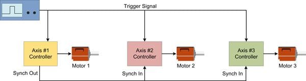
Figure 3. Schematic of Master-Slave Synchronized Motion Control
In such scenarios, one of the controllers is assigned as the master controller that sends out signals for other controllers to sync. The rest of the controllers in the configuration is referred to as slave controllers. They will work in tandem with the signals from the master controller.
Electronic Gearing
In use cases where motors are not directly connected to the end object like a robotic arm, the speed of the motor is not translated to the transmission mechanism it is connected to. For example, if a motor is connected to a conveyor belt, the speed of the conveyor belt is not the same as that of the motor.
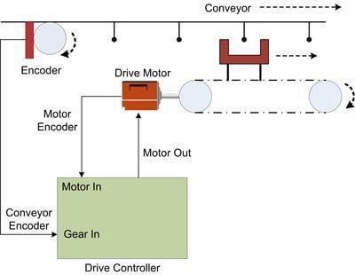
Figure 4. Schematic of Electronic Gearing
Positional data is collected using sensors and sent to the controller as quadrature encoder signals. The motor can be driven according to this quadrature signal. It is not necessary to run all the motors in the same sync. During the design phase, different ratios can be set for different motors, and each motor can be controlled separately running at different ratios with the quadrature signals. For more complex processes electronic CAM can be used which is a more complex gearing system.


Do not use master-slave if the controller is controlling the master. The snych out from the master in the diagram above is the actual position which is not perfect. There is always a little following error or at least quantizing ( feed back resolution ) error, sample jitter and or phase delay from reading the master’s actual position. In the example above the controller is controlling all three actuators so the three actuators should be follow the target position generated by the controller. The target position is usually an almost perfect position because it is a floating point value with very fine resolution, no sample jitter, or phase delay between the three actuators. On top of that the controller usually generates a target velocity and acceleration too which are handy for generating feed forwards.
If the controller is not controlling the master as in example 3 then electronic gearing should be used. A good example is a flying shear similar to example #3 above. Now the trick is to try to generate a perfect target position, velocity and acceleration from the encoder feedback. It is best to use a high resolution encoder that is sampled at consistent intervals so the encoder velocity and acceleration can be determined accurately. Mechanical conveyors are never perfect. There is usually some surging that occurs. Chain conveyors generate jitter as the chain goes over the sprockets. This jitter makes it difficult to computer accurate target velocities and accelerations for the slaves to follow.
Below is an example of electronic gearing. There is a feed chain that is moving the wood through a scanner that determines how best to cut the wood for maximum yield. The wood is not cut straight but in general the cuts follow the grain and the wood is dried out straight later. There are 3 sets of chipper heads that follow the cubic-spline/cam generated by the optimizing computer. Notice that each set of top and bottom chipper heads are delayed by a number of encoder counts before executing their cubic-spline. Unlike the video above, the three sets of chipper heads are not doing the same thing at the same time. On top of that each piece of wood is different so the the 6 cubic-splines are down loaded to the controller for the next piece of wood while the current piece of woods is being chipped. Yes, the is from 2004 somewhere in Canada.
https://deltamotion.com/peter/Videos/JAN-04%20VSS_0001.mp4