 Facebook
 Google
 GitHub
 Linkedin
What is a Variable Frequency Drive (VFD)?
When we need to change the speed of an industrial motor, whether to control a process or save energy costs, we turn to the variable frequency drive, better known simply as a VFD.
In short, a variable frequency drive, or VFD, is a device that adjusts the frequency of the incoming AC current to a 3-phase motor while maintaining the output voltage from the VFD at a stead DC level, ensuring that the motor can respond to adjustments in the desired operating RPM.
But how does a VFD actually work? Where are VFDs used? And how do you properly size a VFD? These are all very good questions, and can’t be entirely explained in one article, but be sure to check out the links at the end of this article for a bit more elaboration on this versatile and pretty incredible industrial control device.
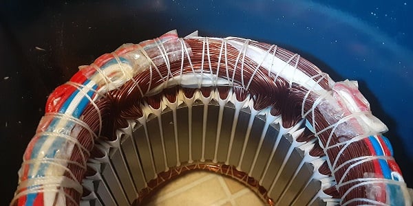
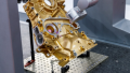
Figure 1. The inside of a 3-phase motor showing the coils. Image used courtesy of the author
How Does a 3-Phase Motor Work?
Perhaps not surprisingly, the discussion of a motor drive unit must first be preceded by a quick synopsis of the motor itself, explaining why such a drive is necessary. 3-phase motors are connected directly to the 60 Hz voltage that comes from the power lines. When the motor gets up to full speed, the alternating direction of the current perfectly polarizes the windings around the outside of the motor in harmony with the speed.
This works great if you plan on always running the motor at full speed, but as you might guess, there are two main problems with this strategy: while the motor is speeding up (not yet at top speed), and when you need to run permanently below full speed. In both of those cases, you will need a device that slows down the frequency of the AC current to an appropriate quantity.
That is the job of the VFD: it reduces the frequency of alternation to the motor windings by using high-current semiconductor switches to deliver the target running speed. Note that although the voltage of the DC bus provided to the motor leads does not change, but the distribution of voltage between the resistance and inductance of the coils does change, and the apparent voltage of the windings will change as a function of Hz, creating the V/Hz ratio we see so often in VFD control strategies.
How Does a VFD Work?
Now that we have established what they are and what problem they solve, how exactly do VFDs perform their intended job?
We know that in order to control the motor rotation, we must reduce the speed at which the current is alternated (flipped directions) as it goes through the electromagnetic coils.

Figure 2. Pulse-width modulation, or PWM, changes the width of the DC bus voltage pulses, allowing the computer to recreate any waveform, including AC. Image used courtesy of the author
As a side note, if the voltage in a motor were to be actually reduced, the motor would indeed spin more slowly, but only because the load is dragging it behind the alternation. The magnets are being polarized as if the motor were spinning at full RPM, but because it does not have enough torque to spin faster, it is losing much of its efficiency and is likely to stop spinning altogether if the load increases.
The method by which the VFD produces the slower frequency is a 2-step process: converting the incoming voltage to a DC bus voltage, then recreating the AC output.
DC Bus Voltage
First, the incoming voltage is rectified, meaning it is converted into a DC voltage. This is why some smaller VFDs can be supplied with 1-phase or even DC power. They can convert all of these into DC anyway.
AC Wave with PWM
To send the DC voltage to the motor, the electricity is pulsed very quickly by switching MOSFETs on and off, in both the forward and reverse directions. The speed of this pulse, or PWM signal, can be designed to act much like an AC waveform. Since the processor is responsible for how quickly the transistors switch, it is quite simple to create lower frequencies than 60 Hz.
More about PWM in VFDs can be found in other articles.
Where are VFDs Used?
Perhaps a better question might be, where are VFDs NOT used? The rising number of electric motor applications coupled with the low cost of most VFDs means that they can be applied to virtually any circumstance in which some level of control is required.

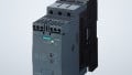
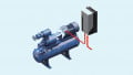
Figure 3. This series of motors is used for variable-speed pumping, and each motor includes an integrated VFD mounted right onto the side of the motor. Image used courtesy of Adobe Stock
VFD in HVAC
Building automation, and air delivery systems in particular, rely on variable speed fans to change the temperature and humidity of zones throughout a building. It used to be that a single speed motor delivered air to all parts of an air handling branch equally, only ON or OFF, but now, with VFDs, the energy efficiency of a building can be greatly improved by running at the lowest required power to ensure comfort.
VFD in Pump Applications
The flow rate of air can be changed with a variable fan speed, and we apply exactly the same strategy to fluid flow from variable speed pumps. When a pump runs at full speed, excess pressure must be exhausted through a pressure relief recirculation valve. All of that excess flow is energy that is wasted. By adjusting the pump speed, the exact pressure and flow rate can be manipulated for energy savings.
VFDs in Every 3-Phase Motor Environment
I cannot describe or list all VFD applications. Just do an internet search for ‘where are 3-phase motors used’ and it is likely that each of those tens of thousands of situations has been outfitted with a VFD more than once.
How Do You Size a VFD?
VFDs are rated most often by the voltage and by the power. Motor power in either HP or kW defines how much current and voltage together will be consumed at peak draw. The voltage of both the motor (VFD output) as well as the supply (VFD input) must be selected before purchasing. For nearly any motor over 1 HP (0.75 kW), both motor and supply will be 3-phase line voltage.

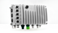
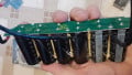
Figure 4. This VFD shows a power rating of 0.75 kW (1 HP) using a single-phase voltage supply. Image used courtesy of the author
Be careful with voltage, because motors can be wired for either 230/240 or 480, and selecting the wrong motor with the wrong VFD output can permanently damage both devices.
There are numerous other options for communication ports, braking resistors, parameter lists, HMI attachments, and more, but those must be selected according to the control system, and are usually not part of the sizing process.
How to Use a VFD
Using a VFD is a topic best left to other articles, since the number of ways we can connect and program a motor drive is so diverse. However, after an introduction to the topic, if you need more information, we have plenty of other articles that explain the ins and outs of working with electric motors and drives.
- Comparing Single-Phase and Three-Phase Motors
- 3-phase Motor Types: Synchronous and Induction Motors
- Common Motor Windings and Wiring for Three-Phase Motors
- Field-oriented Control (Vector Control) for Brushless DC Motors
- The Link Between VFD Skip Frequency Parameters and Harmonics
- Controlling VFDs with Manual Inputs
- Soft vs. Direct On-line Motor Starting


A constant volts/hertz ratio is crucial to the motor when operating at less than ful speed. Ergo, the voltage MUST change along with frequency. The buss voltage remains constant but the apparent voltage changes.