Facebook
 Google
 GitHub
 Linkedin
Dynamic Braking Resistors for Motor Control Applications
Large DC and AC motor drives often provide terminals for installing a braking resistor. What are these resistors, and how do they slow down a machine? What hazards and cautions must be considered?
Mechanical Energy
Any machine in motion possesses kinetic energy. This energy is the result of some stored potential energy being ‘dumped’ into a motor or actuator, causing the energy to be converted into accomplished work. While the machine is in motion, two factors help to determine just how much energy must be dissipated to bring it to a stop: mass and velocity.
High kinetic energy can result from a large mass system or from a high velocity, or both. When the system has a large mass (a large flywheel, heavy drum roller), we refer to this as a high inertia system, meaning that motion will want to continue unless acted on by a significant external force (Newton's second law of motion).
When the kinetic energy and the inertia are both high, as is the case for many kinds of industrial equipment, the process of slowing or stopping the system can be a difficult task.
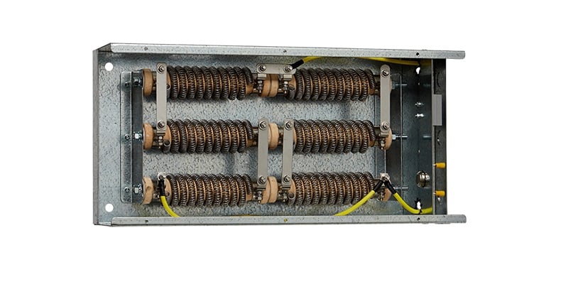
Figure 1. Internal view of a braking resistor. Image used courtesy of Fortress Resistors
Methods of Stopping Free Motion
To stop motion, you only have a couple of options. ‘Stopping’ in a more technical sense means to convert the kinetic energy of the system into other by-products that will lead to a gradual decrease until kinetic energy is zero.
If a device is left spinning, there are a handful of things that can stop it:
- Friction from bearings and contact points (if the bearings are good, this can take a very long time to slow down)
- Air resistance can be surprisingly significant if the geometry of the moving object interacts with the air around it
- If the device is driven from an electrical or fluid system, the machine may find itself trying to reverse-drive the fluid or current. This acts as a form of frictional resistance
In all three scenarios, we must ask one critical question about the kinetic energy. You cannot simply delete energy from a rotating object, so where does that energy actually go?
In all three cases, heat will be generated at the point of energy conversion. If the bearings or the air around the object are the source of friction, that is where the heat will be found. More friction (such as a worn bearing) will produce more heat. This is exactly why predictive maintenance examines machinery for problematic hot points to indicate excessive wear and friction.
In the case of a reverse driving of fluid and current, this can also generate large amounts of heat. Hydraulic fluid, being very viscous, can stop motion much faster and dissipate the heat more quickly, so it tends to be less of a problem. However, in the case of electricity, driving current back into the drive circuitry can be instantly catastrophic for the control system.
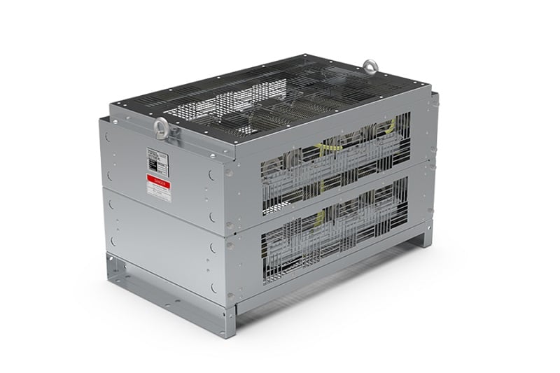
Figure 2. Large floor-mount braking resistor. Image used courtesy of Fortress Resistors
Resistive Braking
One of the most common passive electronic components is the resistor. The simple function of this device is to convert electrical energy (current) into heat. This can accomplish a variety of tasks, such as dividing voltage in a series circuit, limiting current in a solid-state circuit, or simply creating heat in a baseboard heater.
In the scenario with the large load spinning, it is crucial for the kinetic energy to be safely dissipated as quickly as possible, as a long slowdown may mean halted production for many minutes - or even hours. The resistor is an obvious choice for this task, as long as the resistor is properly chosen for the task.
The energy to be lost is tremendous. No small prototype circuit board resistor will be suitable for this job. Those resistors have power ratings between ⅛ watt up to only 5-10 watts for the very largest.
To get an idea of what kind of power rating this resistor might need for the task of braking, imagine a steel flywheel with a diameter of 3.3 feet (1 m) and a mass of 330 lbs (150 kg), rotating at 250 rpm. We wish to slow this down to a stop in 3 seconds.
For rotational motion, the kinetic energy equation follows:
$$Energy = \frac{1}{2} \times Moment~of~inertia \times Angular~velocity^2$$
Moment of inertia for a cylinder:
$$Moment~of~inertia = \frac{1}{2} \times Mass \times Radius^2$$
$$Moment~of~inertia = 18.75~kg \cdot m^2$$
The angular velocity of this wheel:
$$Angular~velocity = \frac{2 \times \pi \times RPM}{60}$$
$$Angular~velocity \approx 26 \frac{radians}{second}$$
Therefore, plugging into the first energy formula, this system has 6337 joules of energy.
This unit, joules, is not a particularly common unit, but when energy is divided by time (the three-second stop time target), we will see the maximum power dissipated in watts.
$$Power = \frac{6337}{3}=2112~watts$$
When examining power braking resistor specification sheets, we should therefore expect to see power ratings in the hundreds to many thousands of watts.
Braking Resistor Connections
You cannot simply install a braking resistor across the motor leads, since this would route power from the drive unit through the resistor. Instead, the drive units are outfitted with brake resistor terminals specifically for this purpose.
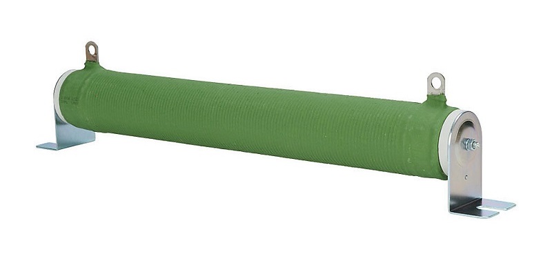
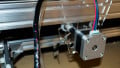
Figure 3. Some braking resistors do not need to be quite as large - smaller mass, velocity, and stipping rate can make a difference. This one is ceramic. Image used courtesy of Automation Direct
Many VFD and DC motor drive units will have clearly marked resistor terminals.
When a controlled stop is necessary, the drive unit automatically switches internal contacts from the driving source over to the output resistor. Suddenly, rather than receiving electricity from the source, the motor power is re-routed through the resistor. The motor is now a generator, and the generator is driving a resistor to dissipate energy faster.
What Does ‘Dynamic’ Mean?
The power dissipated by the resistor is not constant. When the machine is at full speed and the stop is applied, the kinetic energy is at its maximum, so the power dissipated by the resistor will be maximum as well. As the load slows down, so does the energy dissipated.
In our example, it would be erroneous to say the resistor is consuming 2112 watts at all times during the entire slow-down cycle, but it will be at this value for a moment, so the resistor must be sized properly.
Eventually, as the load gets close to stopping, the energy dissipation would be quite small. This total energy consumption is predicted with an integration from calculus (total sum over time when the situation is changing).
In a physical sense, this would appear to the viewer as a large change in speed, and massive heat output from the resistor at the beginning, but would taper off over time.
In modern drive units, the amount of current released into the braking resistor is tuned carefully to control the power dissipation, and therefore the braking effect, so that the dynamic control is made even more useful for a wide variety of cases.
Summary
Braking resistors are useful for large loads. The drive units can take advantage of these devices for more rapid slow-down cycles. In some cases, the energy may not be converted into heat, but perhaps into a battery chagrin circuit. In these cases, we call this ‘regenerative’ braking, used in electric vehicles, train locomotives, and more.