Facebook
 Google
 GitHub
 Linkedin
Understanding Mathematical Units for Electric Troubleshooting in Industrial Environments
A previous article mentions various electrical units used in troubleshooting techniques. This article expands on those and discusses some additional units that engineers may need to know.
It is crucial for engineers to understand basic math concepts and units, as they use this knowledge in their daily operations. In some jobs, engineers are expected to know differential equations and calculus to find and solve complex motor and motion issues.
While this may seem obvious, if an engineer does not use that specific kind of math every day, it can be forgotten. This involves a comprehensive understanding of the units that describe and define the ratings of components.
Mathematical Units for Troubleshooting
The previous article mentioned voltage, current, power, and heat dissipation. This article will discuss additional units including, resistance, impedance, energy (and arc-flash energy), and frequency.
Resistance
Although resistance may not be the first rating listed on most component datasheets, it is most often the culprit for failures and costly damage. Resistance is the voltage required to drive 1 amp of charge between two points in a circuit.
If more voltage is required, that indicates a higher resistance. In wires and other pure conductors, there should be very little driving voltage required, indicating a low resistance.
Nearly every physical change in a circuit is a change in resistance. Input voltages are not often subject to change except for plugging in the wrong power adapter or an occasional electrical power grid surge. Therefore, nearly every other failure is because damage or wear on a circuit has changed its resistance.
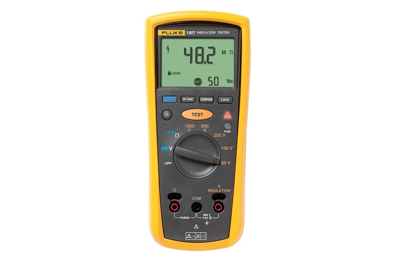
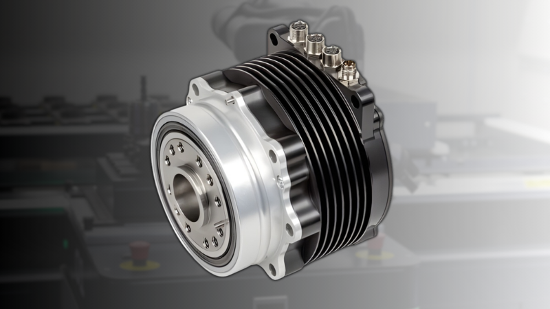
An insulation resistance tester. Image used courtesy of Fluke
If resistance increases, the amount of available current drops would result in a dim light bulb, a bogged down motor or flickering of an indicator light. On the other hand, if the resistance drops, current may be increased.
This current increase can be very problematic. If current goes up, it will usually have an accompanying rise in heat. In a coil-type device, that may be enough to melt some of the thin insulative coating, causing two coils to contact each other and further reducing the resistance and increasing the heat.
Solid-state devices will also see a lowered resistance when heat increases. If this current is not kept in check, it can build and cascade out of control - ‘thermal runaway.’
Impedance
This term is used commonly to express the input resistance of a measurement tool, such as a meter, oscilloscope, or even a PLC input terminal.
The general concept is identical to resistance since impedance is the resistance to current flow in a circuit. However, in a circuit with an alternating AC input, there are added resistive effects of capacitors and inductors on a circuit board, not just the resistors alone.
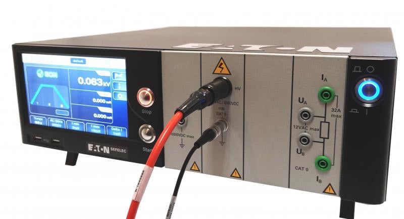
A megohmmeter from Eaton. Image used courtesy of Eaton
Expect this term to appear when AC voltages are a possible input. This is why measurement tools commonly use the term - of course, a voltmeter or oscilloscope would likely measure AC signals. It might also be expected on PLC and data collection modules with AC inputs. This can be important information since it can determine how significantly the device will load down the circuit and possibly influence the results.
Energy
In the sections about voltage and power in a previous article, energy was expressed as ‘Joules,’ but that definition does not appear very often in electrical circuits and devices. Instead, we are more commonly used to seeing energy in ‘kilowatt-hours’ or ‘kW-hr.’ This is not the same unit as a joule, but it represents the same kind of measurement.
Simply put, energy is equal to the amount of work accomplished by any mechanical or electrical process. Energy is both supplied by a source in order to do the work, and energy is converted by the device accomplishing the work.
Energy is also wasted by most of the pieces between the source and the destination - less waste energy equals higher efficiency. We like high-efficiency processes.
If a device is consuming energy at a certain rate, we would say it uses a certain amount of power, for example, 1000 watts. If that power usage is maintained for a long period of time, say one hour, the total energy consumed would be 1000 watt-hours or 1 kW-hr.
Simply multiply that constant or average power by the number of hours. This is further multiplied by the power rate charged by your local energy company to determine your bill for a month.
This measurement of kW-hr is a far easier conversion method than requiring us to mathematically calculate the number of joules used over a month or two. 1 kW-hr is about 3.6 million Joules.
Arc Flash Energy
On most high-voltage control and power electrical enclosures, a label will indicate arc flash hazard. The label will often show a total energy capacity as well as a safe boundary. The boundary will usually be marked on the floor around the cabinet as well.
In such cases, there should be firm safety measures in place, including extensive training and protective equipment worn by anyone servicing the equipment.

Arc flash energy warming label. Image used courtesy of Eaton
The energy unit used in most of these situations is calories per square centimeter or cal/cm^2. This is truly not a formal definition of energy. The calorie itself is an energy measurement, but this is rather a method of expressing the danger of how intense the energy might be to anyone standing nearby.
A huge amount of energy spread over a large area may be harmless (think of the sun’s energy on the earth), but focused on a small 1cm x 1cm area can easily be fatal.
Frequency
Finally, a last common unit is used when voltages are switched on and off, or when they alternate at a consistent rate. The unit ‘Hertz’ or ‘Hz’ represents one alternation per second. For high-speed signals, it may be thousands or millions of hertz, stated as kHz or MHz. Radio waves may be higher still.
In electrical circuits, frequencies of 50 and 60 Hz are common residential and industrial supply voltages. Frequencies in the thousands are generated by solid-state switching drive components (like VFDs) to simulate and recreate variable analog values.
In these VFDs, it may be important to understand the relationship between Hz and performance. The frequency used to recreate AC, if kept too low, can cause a lot of noise from the drive and the motor. But if kept too high, it might cause damage to the motor.
Depending on the situation, it can be helpful to understand how to adjust the PWM carrier frequency on a VFD to drive the system properly.
These units may be helpful in industrial troubleshooting. Depending on the industry, situation, and system at hand, it is important to understand these units and how to read them.
Related Content