Facebook
 Google
 GitHub
 Linkedin
Variable Frequency Drives (VFDs) In Motor Control
What is the purpose of a variable frequency drive? How do they work? And why would we prefer using VFDs over basic motor starters for heavy loads?
The variable frequency drive unit solves the challenges of driving a 3-phase motor with careful speed control and efficiency, without being overly cost-prohibitive in most cases. They can be configured to run in applications spanning from small standalone machine centers all the way up to vast networks of huge machines.
What Is a VFD?
In short, the VFD receives power from a stable 50/60 Hz AC supply, and converts it to an output that mimics an AC waveform, but at frequencies that can change, giving the name variable frequency drive.
The input voltage of the VFD can be either single-phase 120-240 VAC, or three-phase 208-480 VAC, or sometimes even higher. The single-phase input models are great for small motors since you don’t need to have a 3-phase supply to run the motor.
The input AC power is converted to DC through a rectifier and a filter capacitor. This provides a constant DC voltage at a level matching the motor's rated voltage level. To run the motor, the DC voltage is pulsed on and off at a very high frequency, usually in the thousands of Hertz. The ratio of on vs off time of each pulse will allow the current to increase or decrease. For example, if the pulse is on 90% of the time and off for the remaining 10%, the current would be expected to be nearly maximum.
This rapid series of pulses varies in percentage between 100% off and 100% positive, then back to 100% off, then 100% negative, and repeats.
The speed at which these percentages complete a full cycle can be set anywhere between 0 and 60 Hz. Or, it could be commanded to ramp up to 60 Hz at a set rate when turned on. At this point, there’s a wide variety of control options.
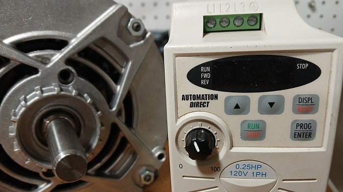
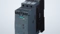
Figure 1. The VFD is responsible for driving many 3-phase motors.
Notice in the above figure, we see only two screw terminals plus the green ground. This arrangement indicates a single-phase input. Also, the small network port is for RS-232 communication, not Ethernet control in this case.
Why Do You Need a Variable Frequency Drive?
When it comes to moving the big loads demanded for industrial operations, the 3-phase motor is usually called to the plate as the heavy hitter. They use less current than single-phase motors with equivalent horsepower, since the voltage is higher. In addition, the single-phase motors are far more difficult to start and run in a controlled direction. Brushed DC motors, which are another popular alternative, run less efficiently due to the wear and tear of the carbon brushes that provide the rotation of the magnetic.
Although 3-phase motors have many advantages, there are some added difficulties when it comes to operating them. Simple motor starter circuits allow us to connect two of these starters, interlocked with each other, which can start and run the motor in either direction with two of the phase lines reversed. However, starters are limited to only fully on/off operation. When turned on abruptly, the motors can consume massive amounts of current, leading to increased utility costs.
Another disadvantage in large applications is the result of small fluctuations in the main voltage, such as caused by other devices in the facility turning on. In an analog starter circuit, these fluctuations are passed right to the motor coils, causing small imbalances in an otherwise smooth rotation.
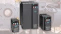
This model does not have buttons or a screen on it, so programming must be done through a communication port.
How Do You Control a VFD?
Depending on the application, VFDs can be controlled with a variety of control schemes.
Sometimes they are tasked to run a single, stand-alone machine, with very limited human interaction. Most VFDs have a small screen on the front, called a human-machine interface (HMI), which may have some digits to display information, or perhaps a color touch screen. There will also likely be a start and stop button, and a rotating potentiometer for speed control. Controlling it from here is called “Local” control.
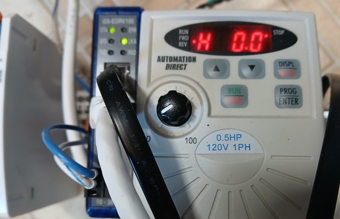
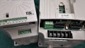
Figure 3. Local control options from the on-board HMI.
There’s another very common way to control VFDs on stand-alone machines. Most VFDs will have a row of small screw terminals or a small multi-wire connector located under the cover. These connection points allow digital inputs, in other words, push buttons for starting, stopping, and directional control. There’s also an analog input for an external potentiometer. All of these inputs allow the VFD to be safely tucked in a control enclosure, with well-labeled buttons on the outside, keeping the operator isolated from the 3-phase power inside the cabinet.
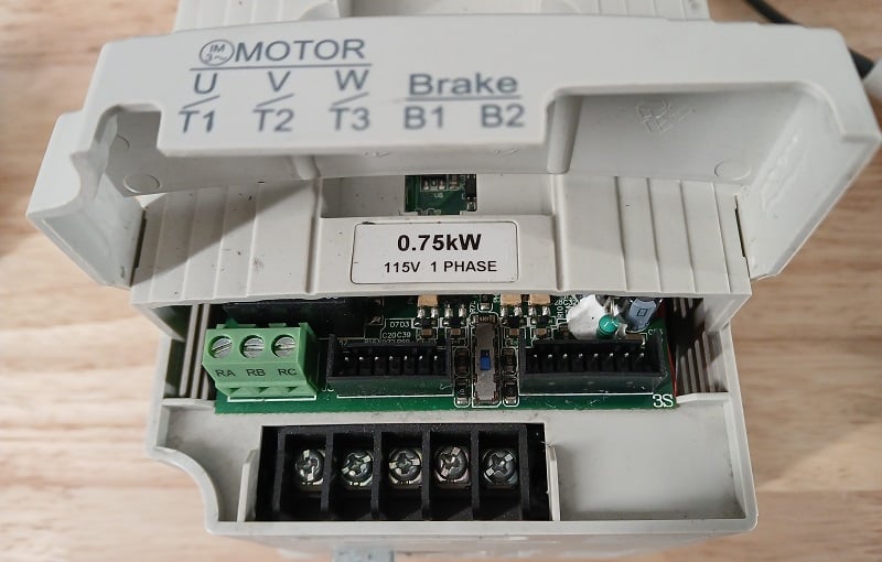
Figure 3. Digital input terminals to enable simple remote control for the VFD.
In some cases, these digital and analog inputs can be provided by a digital controller like a PLC, allowing even greater control.
For a large-scale implementation, it’s more common to have all operations of the VFD controlled over a computer network. Ethernet, PROFINET, DeviceNet, EtherCAT, and others can communicate with many VFDs. Network functionality is usually a standard feature in modern VFDs, but in many cases, the network connection is an add-on module connected with a ribbon cable or pin header set. In these cases, a single network cable connects to the drive unit, and all motion can be controlled and changed remotely.
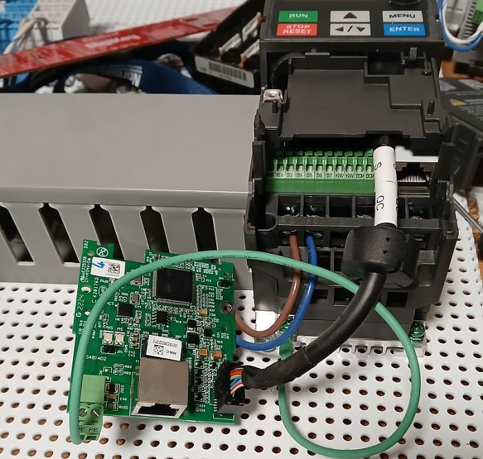
Figure 4. Add-on communication module for enabling Ethernet control.
One thing to note: Be careful when connecting Ethernet cables to make a connection. Many times, an RS-232 connector may also use the same 8-pin RJ45 jack, which looks like an Ethernet port. The RS-232 protocol is used for programming, not operation; you can’t simply connect an Ethernet cable. Make sure to verify that it has the proper network protocol.
The Benefits of a Variable Frequency Drive (VFD)
To combat the limitations of basic motor starters, this digital control device is employed to allow much better control.
First, you can access some basic feedback about your system, even without sensors. It monitors the current provided to the motors and can display faults if the current exceeds acceptable levels.
It is also possible to adjust a great many of the operating parameters which control how the motor runs. You can adjust the start-up acceleration and the deceleration times (ramp rates), the maximum speed, in cases where full rated RPM is too fast, and many other options.
A final surprising benefit is the low cost of these devices. A pair of small starters, along with the buttons required for manual control, can cost hundreds of dollars or more. A comparable VFD for a small horsepower motor, with the buttons integrated right into the front, can still only cost barely more than a hundred dollars. The costs can escalate drastically for larger applications, but the complexity of the device alone does not mean it’s prohibitively expensive.
One thing to note about VFDs during the application process is that they can easily run a motor at a lower frequency (and therefore RPM) than its rated value, but you should be very cautious when trying to run it faster. Although it is theoretically possible, the motor is designed to run only at a maximum RPM. Running the motor faster can cause heat, reduced efficiency, and a shortened life.
There is no doubt that VFDs will continue to increase in popularity and application cases, and understanding their operation is a very valuable asset.
Check out more of our VFD content on Control.com:
- Control Wiring for Variable Frequency Drives (VFDs)
- Controlling VFDs with Manual Inputs
- The Link Between VFD Skip Frequency Parameters and Harmonics
- Teardown: What's Inside a Variable Frequency Drive (VFD)?
All images used courtesy of the author
Original article published Feb 2020