Facebook
 Google
 GitHub
 Linkedin
Controlling VFDs with Manual Inputs
To increase the flexibility of a motor control system, a variable frequency drive (VFD) is a common device that solves many motor control problems. In this article, learn how to control manual input of VFDs.
Variable frequency drives solve many of the challenges associated with driving three-phase motors including adjustable speeds, networking many motors together for an entire process, and finally the ability to adjust operation without changing the wiring. However, for simple operations, these drives can still use the same manual pushbutton controls used in motor starting circuits, but with additional abilities.
Driving three-phase motors can be a very simple process with the right equipment. Manual control circuits including contactors and starters can be quite inexpensive, but they are limited in a number of ways. First, these circuits do not drive motors at anything less than full speed. Also, if you want to change the pattern of operation, you must re-wire the entire control circuit.
To increase the flexibility of a motor control system, a variable frequency drive (VFD) is a common device that solves many of those motor control problems. In particular, a VFD is one of only a few options when varying speeds are required for operation.
Fortunately, using a VFD does not require a PLC or giant networked control system. But if a larger control system doesn’t exist, the VFD provides a simple option for integrating the motor into a future control system. Future-proofing a system is very useful, especially when it is not very expensive.

Figure 1. Two examples of VFDs showing the control terminals as screw terminals (Left) and pre-wired connectors (Right). The exact function of each terminal is selected from within the parameter menu.
Using simple, manual control elements like start/stop buttons, direction switches, and speed control are not very difficult to connect to a VFD. Although there are many brands and models, the general strategy is the same across all VFDs. For proper operation, two distinct elements must be considered: The Wiring, and the Parameters.
VFD I/O Wiring
Every VFD will include a set of terminals allowing a user to connect I/O wires. Typically, these will be on the same 24 vDC system as the remainder of the control system devices. The wires may be attached directly to a screw-down terminal block, or it may be a set of one or more pre-wired connectors on the circuit board. Be sure to use at least the minimum wire gauge size for these control wires, but they can be very small since very little control power is used.
With a single N.O. button, an N.C. button, several selector switches, and a potentiometer, nearly any variety of control scenarios can be connected.
First, identify the wiring diagram, which might be found online or in the included documentation. The diagram should reveal several terminal functions:
- A power supply terminal should be indicated with 24 volts
- The common ground, or COM
- A 10-volt output is often provided for the analog speed control device
- The next set of terminals are Digital Inputs, perhaps ‘DI’ or ‘In’ and there are often four to six of these terminals
- A single analog input which might be labeled as ‘AI’ or ‘V’ for voltage
- Many VFDs also include an electromechanical relay to provide output information, toggling based on certain operating points
Digital Inputs
If the VFD is set up as a ‘sourcing’ or ‘sinking’ wiring type, it must be noted in order to correctly connect the wires. Some VFDs have a toggle switch to select which type, while others are set simply by connecting the power supply in whichever scheme is most appropriate.
If the VFD is set for ‘Sinking’ type wiring, then each control device should be connected to the positive voltage. Each device also then connects to its appropriate digital input terminal. Often, but not always, the first terminal is always connected to the STOP normally closed button. The actual function of each digital input will be configured by the parameters, later on.
If the VFD is set for ‘Sourcing’ wiring, the same above is true except that COM is connected to each device instead of +V.
One important note: Some VFDs require the connection of a wire or N.C. switch to the stop terminal for safety reasons. In these models, even if it’s used with network control, a wire must be spanned from the +V terminal to this input.

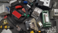
Figure 2. Several of the input devices that may typically be seen connected to a VFD. In particular, note the potentiometer knob with the three wires at the bottom-left corner of the picture. This common analog device is used to control speed.
Analog Input
The analog input, such as a rotating potentiometer knob is a classic, easy method of choosing the speed of the motor. For the three-terminal potentiometer, terminals 1 and 3 will connect to the 10-volt source and COM. The order of those will determine whether rotating CW or CCW will speed up the motor. The second terminal (2) should connect to the ‘AI’ or ‘V’ terminal.
Sometimes this analog voltage signal can be sent from a PLC or simple 0-10v controller signal, allowing the VFD to work in a huge variety of scenarios.
Parameters
Every VFD is customized based not on the I/O wiring but on a menu of parameters that control how each terminal affects the operation.
A set of buttons on the front of the unit is almost certainly the way to access the parameters, but the manual should be consulted to determine exactly how the structure works. Every VFD is completely different as far as how many parameters exist, how to access them, what the default values are, and how each operating mode is represented.
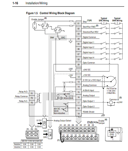
Figure 3. This excerpt of a PowerFlex 40 VFD manual shows the digital input terminals, as well as the selector switch togging between Sinking (SNK) and Sourcing (SRC) wiring at the very bottom. The function of the digital inputs is the job of the parameters (specifically A051 to A054 in this unit).
Regardless of the make and model, there are a number of similarities.
First, the control parameter must be set to use the input terminals — NOT local control (the keypad) and NOT network control (Modbus RS-485 or Ethernet for example).
Next, the digital input parameters may determine between several modes of operation:
- Forward with one DI terminal, Reverse with another
- Stop and Start, single direction
- Stop, with toggle switches for Forward OR Reverse motion
- Stop, with a start and a manual directional control toggle
- Stop and Start with a couple of toggle switches used to select between different pre-set speeds
- Stop with Start or Jog, selectable with a toggle switch
There may even be a few extra benefits available with these digital inputs:
- Fault reset
- Incrementing or decrementing the speed
Summary
If flexibility is a requirement for motor control, the VFD may be the best way to go. It can also be integrated into nearly any existing control system, or a new control system can be constructed around an existing VFD.
Related Content