 Facebook
 Google
 GitHub
 Linkedin
How Pulse Width Modulation is Used in Variable Frequency Drives
In this article, learn how variable frequency drives make use of the principle of pulse width modulation to create analog-type signals from a digital source, such as with motor drives.
Pulse Width Modulation, or PWM, is a commonly used strategy for creating analog types of signals from a digital source. This is a common method when trying to drive motors from a source controlled by discrete transistors, incapable of providing a specific variable current output. Variable frequency drives make use of this principle in order to operate.

Figure 1. An example of a small variable frequency drive. Image courtesy of C.J. Cowie. [CC BY-SA 3.0]
Many controller outputs make use of a strategy of pulsing on/off signals to provide a limited amount of current to a load device. This process of pulsing the voltage allows discrete digital outputs to drive analog devices, although still not creating a true analog output voltage.
This method is particularly common in motor outputs due to the power required to drive the loads of the motors. In order to drive with the proper torque and speed, a certain amount of power must be delivered to the motor. That power is a product (multiplication) of both voltage and current. If the voltage is reduced, the power will be directly affected, therefore we cannot lower the voltage and still expect to have the required torque to move the load. So as a speed reduction method, lowering the voltage is not practical. That concept is really only seen in cases of reduced-voltage startup methods.
In order to overcome this challenge, there must be a way to deliver full voltage and current, yet somehow reduce the driving speed of the motor. In a DC motor, such as a hobby motor, this can be done by reducing the average current driving the magnetic field in the rotor which will dictate how fast the brushes commutate. The technique of Pulse-Width Modulation (PWM) quite simply accomplished this task.
In a three-phase AC motor, a simple pulsing of voltage will not change the speed because, in order to operate properly, the voltage must also change polarity. To be precise, it must do so at a very specific frequency to obtain the correct output RPM. This is unlike the DC motor, in which the speed of rotation automatically controls how fast the brushes reverse, sort of like automatic feedback. The AC motor on the other hand must be alternated by an external source.
How Does PWM Work?
There are two key concepts that must be remembered in order to understand how the pulsing concept works. First, a constant PWM carrier frequency controls the calculation of voltage duration. This frequency must be high enough that the output device cannot physically turn on and off with each pulse. If it did so, it would result in a pulsation of the motor which can cause damage. The good news is that motors have a relatively slow reaction time to applied current, so the PWM carrier frequencies do not have to be extremely high but often reside in the area from several hundred Hz up to several 10k Hz.
For reference, small controllers such as the popular Arduino Uno microcontroller, the PWM carrier frequency is about 500 Hz for most of the pins. On the Allen-Bradley PowerFlex 525 VFD, the Carrier Frequency is defaulted to 4kHz. For many industrial drives, the frequency should be matched to any installed line filters.
With this constant frequency, a digital DC voltage may be turned on for a part of this time, then turned off for the remainder of the time. For example, with a 1 kHz carrier frequency, the time for each cycle would be 1 millisecond. The DC voltage may be turned on for 0.5 ms, then turned off for the remaining 0.5 ms. The load would respond with driving briefly, but if this constant on/off/on/off pattern is repeated, the overall response would be exactly half of the maximum response RPM of the motor. If the ‘On’ duration of the pulse is increased, the faster the motor will spin, until it finally reaches full voltage for the entire cycle which is the same as simply supplying a constant voltage.
The ratio of the duration of the ON pulse divided by the TOTAL cycle time is called the ‘duty cycle’ of the PWM output, and is expressed as a percentage from 0%-100%. For DC motors, a constant duty cycle yields a constant, yet precisely adjustable speed.
How Does the VFD Control an AC Motor with PWM?
For the three-phase AC motor, each phase input may be considered individually. In reality, each phase is delayed 5.55 ms behind the previous (⅓ of a 60 Hz cycle), but each phase is simply a copy of the original PWM concept.
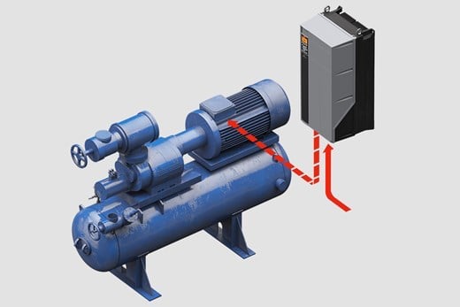
Figure 2. In a VFD-controlled three-phase AC motor, each phase is a copy of the original PWM concept. Image courtesy of Danfoss.
First, the voltage must alternate polarities in order to create the needed AC wave, so the transistors (MOSFETs) driving the outputs are attached in a reversing configuration called an ‘H-Bridge’ which allows the controller to change the output polarity at just the right moment to re-create a 60 Hz signal.
When the digitally-created AC wave begins, the duty cycle is virtually 0% (so there is no current), but it begins to increase very quickly. The rate of change slows down as it climbs toward 100%, in fact, the profile is an exact sine curve, just like the main line voltage. The duty cycle itself corresponds to the average current being supplied to the motor coils, so we will expect to see the magnetic fields of the coils changing at a very precise rate.
For a slowly-rotating motor, the rate of increase of the duty cycle will be relatively slow. As soon as it reaches 100%, the duty cycle will immediately begin to drop back to 0%. Then the polarity will flip, and the cycle will repeat.
One of the easiest ways to consider the PWM output of a VFD is to look at a standard AC voltage curve. But rather than reading it as ‘Voltage’, instead, read it as ‘Duty Cycle’.Since the duty cycle is digitally created, it can be created very slowly or quickly depending on the needs.
You should not try and run a motor at a higher frequency than the dataplate maximum, but the PWM carrier frequency will be many times greater. Also, it is important to note that higher carrier frequencies can generate more interference and electrical noise, but a lower frequency will allow a higher amount of current through each transistor in each PWM cycle and generate a lot more heat. Therefore, yous should pay attention to the manufacturer’s recommendation on the carrier frequency.


Good article. One minor thing I’d point out is that there are many types of transistor that would be capable of producing a fully analog drive waveform. However, the major appeal of switching semiconductors fully on or fully off is that the voltage dropped across the devices is at minimum during conduction and the current through them is negligible when they’re turned off. In both states, therefore, they dissipate the least possible power. In an analog drive mode, there would be a significant combination of voltage across and current through the devices for most of the cycle. Consequently they would be absorbing significant power.
A theoretical analog VFD could produce lovely low-distortion sine output with none of the nasties associated with switchmode operation - but efficiency would be absolutely horrendous.