 Facebook
 Google
 GitHub
 Linkedin
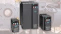
Teardown: What’s Inside a Variable Frequency Drive (VFD)?
Variable frequency drive units can be found inside tons of control cabinets, but what happens if you disassemble one to see what’s inside and how it works? We did just that. The results might surprise you.
Here at Control.com, we’ve been on a bit of a variable frequency drive (VFD) kick recently, but who can blame us? Driving 3-phase motors with networkable, digital controllers is pretty cool!
On the outside, these frequency drives are boxes of plastic with PCBs inside, providing access to digital I/O terminals, network ports, and the input and output power terminals. If you dig beneath the plastic exterior, however, you can see the components inside and learn how this thing actually works.
For this reason, we decided to disassemble one of our VFDs so you don’t have to.
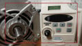
Human Machine Interface (HMI) on a VFD
The top layer of any VFD is a forward-facing HMI, usually with push buttons and a display. In modern VFDs, these might even be touch-screen capable. This device provides access to monitoring critical stats and changing process parameters.

Figure 1. Slot for HMI or blank cover to prevent access.
Once the programming is finished, these HMIs can be replaced with a simple blank cover or a cover with only display abilities to prevent unauthorized adjustment which can create hazards.
I/O and Network Connections
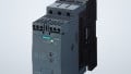
Behind this top layer lies the PCB with the connections for the digital inputs and outputs and for the network interfaces. Sometimes, the network interface may be located on an add-on card, but it is common to find Ethernet and serial ports embedded directly into the module.
This VFD model is a bit older and contains an RS-232 port (gray RJ12 box at the bottom of the PCB), headers for digital inputs and outputs (the black pin headers at the top), and a relay connection (the green screw terminals at the top) that can be configured to provide an output when speeds are reached or when faults occur.

Figure 2. Digital I/O and network interface PCB.
Like many others, this VFD also has a selectable switch that can toggle between accepting NPN or PNP input sensors. This switch is located between the two black headers, and a drop of yellow glue shows that this VFD has been purpose-built for one application and was not meant to be adjusted.
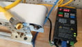
Power Connections
In any VFD, power must be both provided into the device and sent out of the device on its way to the motor. The input might be either 1-phase or 3-phase, but the output is always 3-phase.

Figure 3. Power PCB (right side of image) with connections for line input, motor output, and optional braking resistor.
Two larger screw terminal headers are designed to accept the larger amount of current that will be expected for this model of VFD, built to power up to a 1 horsepower (750 W) motor. This PCB interfaces with the digital I/O and network board on the left side of the picture. The digital controls select the proper operating logic, but the logic must then be sent to the power components to operate the correct switching patterns. The 1-phase input is the set of screw terminals at the bottom (including the green ground screw). The power outputs to the motor are at the top.
Two additional terminals are in the top header that provide connections for a braking resistor.
IGBT Motor Driver
The actual driving force behind these VFDs is a module of transistors—specifically, they are insulated gate bipolar transistors (IGBTs). This module by Infineon contains the six necessary IGBTs that provide power in both the forward and reverse directions for each of the three output phases.
The image below shows the PCB with the power headers simply flipped over—this is the bottom side view of that board.

Figure 4. Infineon IGBT module.
The term ‘insulated gate’ means a very high resistance on the control circuit input of the semiconductor. High resistance leads to very low current and a faster switching time—excellent for a pulsed digital output. The high resistance in the control circuit is paired with an extremely low resistance in the power circuit. Resistance leads to voltage drop which leads to heat. While there may be very little resistance, it is still significant enough to require a heat sink.
Contactors and motor starters, in contrast, have virtually zero resistance in the contacts, and therefore, dissipate virtually no heat so do not require heatsinks.
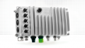
Heatsink and Fan
This IGBT module is attached to the heatsink through an electrically insulated but thermally joined junction. The large aluminum fins of the heatsink pull the heat away from the transistors, and the fan forces cooler air over the fins.

Figure 5. Installed heatsink and fan. The capacitor bank (discussed later) can also be seen.
Two main problems can prevent proper cooling and premature failure. The first problem is a lack of proper ventilation. If the VFDs are mounted too close to other components, or inside an enclosure that cannot properly vent the air, there will be limited cooling.

Figure 6. Aluminum heatsink. The dust buildup on the bottom indicates a dirty operating environment in its previous life.
The second problem is the failure of the fan itself. In dusty environments, the bearing can wear out and stop operating. This VFD, along with most others, has a removable red and black wire so the fan can be replaced with relative ease. Keep your ear out for grinding noises when the VFD is running, as this might indicate that you should replace the fan before the VFD fails at the worst possible time.
Bus Filtering Capacitors
The final layer of this VFD is a bank of capacitors—six of them in this case—all wired into a set of two parallel resistor banks. These capacitors create a smoothing, or filtering, effect for the voltage that comes into the VFD, being immediately converted from an AC sine wave into a single-directional, but still fluctuating, waveform.

Figure 7. Capacitor bank to smooth out the DC voltage ripple
Once the DC voltage is smoothed into a constant voltage, the current can be directed back through the IGBT module to recreate the AC output.
Sometimes, when electrolytic capacitors sit for a very long time (years), they can become dry. It is a good practice to fire up a VFD every once in a long while to ensure that the capacitors will be in good working order when it comes time to call the VFD back into service.
VFD Parts Review
We have seen the parts of a VFD, both logically and visually, as the control logic drives a motor. The power connection PCB receives the input line voltage, converts it into DC with the help of the capacitors, receives a control signal from the digital I/O board, and then recreates the output AC pattern through the IGBT module, which is properly cooled.


Very well explained. Couple of things I would like to add. When the input supply is single phase, the recreated 3 phase at the motor still has the same supply voltage as single phase. In my experience VFDs do not increase the supply voltage (for example single phase 230V input supply produces, 3 phase 230 V). This is an aspect electricians needs to be aware - this is not equivalent to normally available 3 phase (which could be 400v 3 phase). Modern VFDs have come a long way from earlier VFDs, now the VFD can almost do a mini- PLC’s work, including ethernet communication, PID control (without the needs of external controller or PLC), because of ethernet communication, it can also report back many parameters live which could be useful for monitoring/fault finding. Many modern human interface devices have the capability to store parameters, which could be useful to copy to other similar VFDs. Number of parameters are quite high, often in 100s. Finally though the VFDs have become almost essential in speed/torque/position control applications, the harmonic disturbance that they are introducing is becoming a problem, affecting mains supply’s sinusoidal form, which adds to problems of additional neutral current, pulsating torque disturbance in motors etc. Many manufacturers are suggesting adding dynamic harmonic correction equipment (which is often difficult to justify for investment), I feel in future, the VFD manufacturer should introduce counter measures within the VFD to reduce harmonics disturbance in the supply lines.