Facebook
 Google
 GitHub
 Linkedin
Control Wiring for Variable Frequency Drives (VFDs)
Many VFDs use digital inputs to control operation, rather than PLC-driven network communications. Learn about 2-wire and 3-wire digital input control schemes for ABB, Omron, Rockwell, and others.
Nearly every variable frequency drive (VFD) contains a set of screw terminals or pin headers that are designated with analog and digital I/O functions. Even in the modern world of advanced network capabilities, many VFDs, especially those commissioned in smaller or more remote applications, rely on digital input devices to drive operation.
Any control device (industrial sensors or buttons) can be wired to the generic I/O terminals, but it's the programmable parameters that dictate the role of each input, allowing us to switch from 2-wire or 3-wire control, or provide start, stop, forward, and reverse input commands.
Digital I/O Terminals on VFDs
First, let’s cover the basic principles of these control signal headers. Not every screw terminal or pin is designated as a digital input—many VFDs will only have between 2-4 digital inputs. The remainder of the terminals supply voltage and common reference to connect the digital and analog devices.
As an example, the Rockwell VFD, the Powerflex 523, is a common modern example that resembles most other Rockwell VFDs. In this model, the I/O terminal block contains a programmable relay, digital inputs, and analog/com signals. The digital signals on terminals 01-06 and 11 are the most important to us today.

Figure 1. Rockwell PowerFlex 523 I/O terminal block example. Image (modified) used courtesy of Rockwell Automation
According to the listed function, terminals 02, 03, 05, and 06 all state ‘DigIn TermBlk xx’, which means they are digital inputs and can be programmed. By default, they do have some standard functions, but after commissioning, it’s likely that these are no longer the default.
Two other terminals are very important to understand the big wiring picture. Term 04 is the common return for ground. If the Dig In terminals are supplying voltage to a switch (sourcing), the switches must be connected to term 04 to complete the return to ground. On the other hand, if the switches are connected to term 11, which supplies them with 24 volts, the Dig Input terminals return the circuit to ground (sinking). This is the reason why these VFDs provide a switch to toggle between functions.
If this sourcing and sinking terminology is confusing, we recommend downloading and reading our free eBook that explains these terms for control engineers.
2-Wire Start-Stop Circuit Wiring
A 2-wire circuit is intended for one signal to run a function, and if that signal is removed, the function stops. This is different from start/stop latching functions, which are known as 3-wire and will be explored later.
In a VFD, this 2-wire functionality comes in two forms: uni-directional and bi-directional. Since VFDs can easily drive motors in Fwd or Rev, we may choose to have a single input that will drive Fwd or one to drive Rev. Finally, we may have two inputs to choose either Fwd or Rev. All of these, being momentary inputs (like a jog function), are considered 2-wire.
Although the specific terminals vary by model, the basic wiring concept is the same. For 2-wire forward control, a single digital input device is connected to one of the digital inputs, often one of the very first I/O terminals.
For 2-wire reverse control, the single digital device is wired to the same input or to another one. It may appear exactly the same as 2-wire forward control. The difference lies in setting parameter values to pick the direction of motion when the run command is given.
For the final bi-directional 2-wire control, we must use two different digital input devices wired to two digital inputs on the drive unit. As before, parameters control the method of operation as well as where the wires should be placed.
2-Wire Control Examples
As an example of this control, let us examine the Commander S100 drive by Control Techniques. This drive has 5x digital inputs, each with a factor-specific default function. Figure 2 below shows the default configuration. A digital device connected to Dig Ins 2 and 3 will allow 2-wire bi-directional control.

Figure 2. Commander S100 I/O from Control Techniques. Image (modified) used courtesy of Control Techniques
Many VFDs, including the above, also require a constant signal to an ‘Enable’ or ‘Stop’ input which must receive a sustained active control signal, or the drive will come to a stop, providing safety that overrides the digital inputs.
This next example from ABB shows the default digital input assignment, with the first input functioning as the start/run input and the second input as the direction control.
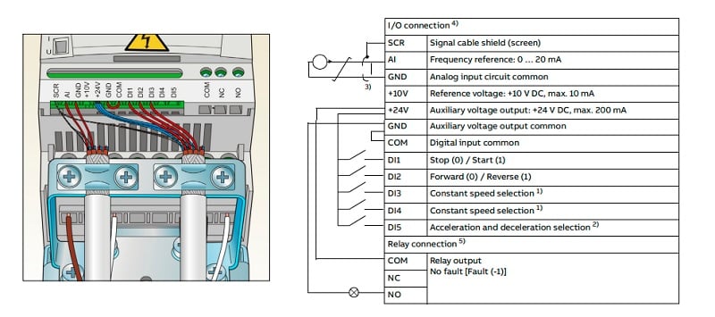
Figure 3. Default digital input assignment for ABB ACS150 VFD. Image (modified) used courtesy of ABB
When Is 2-Wire Control Used?
This scheme is convenient when the VFD is applied to a simple situation where this basic forward and reverse is used. At its most basic level, the inputs could be selector switches on a control panel, or they may be sensors or even an external controller that might not have modern communication signals. I have successfully connected VFDs in this manner to micro PLCs like the Allen-Bradley MicroLogix with no network capabilities.
3-Wire Start-Stop Circuit Wiring
After discussing the 2-wire control, this 3-wire strategy is quite similar. This scheme is derived from a common circuit known as ‘latching’ or ‘seal-in’ in addition to 3-wire. A start and stop button are both provided for convenient latching control—the signals do not need to be sustained, such as for 2-wire.
For 3-wire uni-directional control, a normally closed ‘stop’ signal is connected to the enable/stop digital input. A second device is connected to the next digital input to function as the ‘start’ signal. They operate exactly as they sound—press ‘start’ to start and press ‘stop’ to stop.
3-wire bi-directional control is very similar with the addition of one toggle signal to select between fwd and rev directions.
3-Wire Control Example
The following figure illustrates how to use 3-wire control with an Omron MX2 VFD. In this drive, there are seven programmable digital inputs labeled S1-S7. Choose any three inputs, and assign those inputs with STA (start), STP (stop), and F/R (direction) using the parameters C001-C007. Note the STP input must have the sustained control signal, or the drive will come to a stop.

Figure 4. Omron MX2 VFD 3-wire inputs and parameters. Image (modified) used courtesy of Omron Automation
When Is 3-Wire Control Used?
This scheme closely resembles 2-wire control in application as well. However, the main difference in the latching function allows a short pulse to activate and stop the drive. Perhaps a switch or sensor must be tripped to start a conveyor until a separate input triggers a stop. This is ideal for 3-wire control when network signaling is not an option.

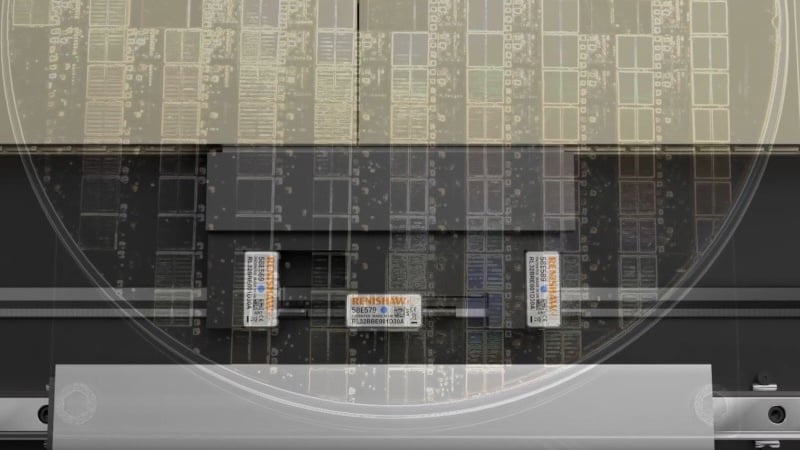
Figure 5. VFDs can be used in nearly every industrial induction electric motor drive scenario.
VFD Digital Control Signals
These startup wiring strategies represent only a small sample of the many control signal function in VFDs. There are selectable speeds, accelerations, fault resets, and many others that cannot be covered in a single article.
An understandable design consideration for motor drives is ease of setup and replacement, and this is clearly illustrated in the wiring diagrams for simple wiring and startup.
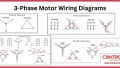
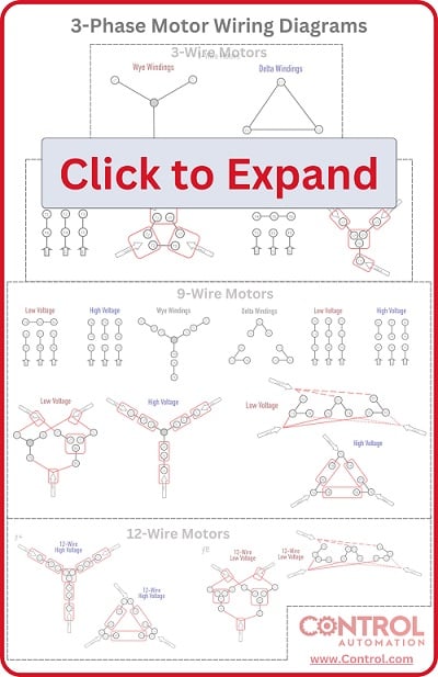
Psssst, hey you... Looking for more info about motors and motor controls? Have a look at this handy wiring infographic and other links below.
Articles:
- Comparing Single-Phase and Three-Phase Motors
- 3-phase Motor Types: Synchronous and Induction Motors
- Understanding Delta Wound Motors for Industrial Applications
- Brushed vs. Brushless DC Motors
- Field-oriented Control (Vector Control) for Brushless DC Motors
- Teardown: What’s Inside a 3-Phase Induction Motor?
Textbook: