Facebook
 Google
 GitHub
 Linkedin
The Link Between VFD Skip Frequency Parameters and Harmonics
Variable frequency drives (VFDs) can output simulated waveforms of nearly any frequency. However, in order to be truly useful, harmonics and resonance in the system must be avoided and frequency parameters should be put in place.
Variable frequency drives (VFDs) are one of the most common methods of driving three-phase motors. The output is a simple pulse of DC voltage, slowly increasing and decreasing in duration to replicate an AC current signal. With the complex processing inside the VFD, it can output simulated waveforms of nearly any frequency — but just because a certain frequency is possible, doesn’t mean it’s a good idea. Some frequencies can result in excessive vibration from harmonics and resonance in a system, but VFD designers have allowed some methods of reducing this problem.
The purpose of a VFD is to simulate the supply of a typical three-phase system, only with the added flexibility of changing the speed of the motor by varying the frequency of the simulated output (as the name suggests).

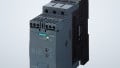
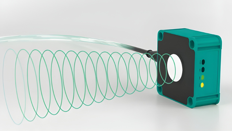
Figure 1. Variable frequency drives simulate the supply of a typical three-phase system, but harmonics and resonance can be an issue.
This is an ideal method of starting and driving a motor since starting speed and torque can be controlled and kept to an acceptable level. However, there can be some disadvantages to this process of speeding up or slowing down a motor.
There are actually two frequencies that are critical in the operation of a VFD. Both can be controlled from the parameter list, since there are related, yet different problems that appear as a result of some undesired frequencies. These two frequency values of the Hz output of the current signal (often displayed right on the VFD) and also the PWM frequency which provides the pulses of electricity. Both will be discussed in depth.
Three-Phase AC Hz Output
Inside the VFD, there is actually a converter that turns the input AC into DC. This DC is then carefully pulsed at a high frequency but is left on and off for varying ratios. The result is a current that can increase or decrease going to the motor. Usually, to ensure safe operation of the motor, the frequency should NEVER be driven higher than the operating Hz of the motor (50 or 60 Hz).
The time duration of the motor acceleration and deceleration is carefully controlled, and in typical across-the-line starting, the motor ramps up as fast as possible, drawing tremendous current. A longer accel and decel time will decrease the current consumption at startup. Usually, this is just fine, but particular frequencies may cause mechanical problems.
Every system has some spring constant - either by actual mechanical springs or by the natural elastic properties of the components. This spring factor can’t be avoided. Every spring factor has natural resonant frequencies, where an input of force at just the right repetition will cause each ‘bounce’ to increase, perhaps out of control. This is a resonant frequency, and it can be calculated with various advanced system dynamic theories, but more likely, the frequency will be noticed as an increase in vibration of the system for a brief time as the motor moves through that exact RPM as it speeds up and slows down.
This resonant frequency may also be seen as an increase in current at a particular RPM since current can be monitored right on the VFD display.
Since equipment is usually made out of distinct but connected sections, there may be more than one resonant frequency — even one system may have multiple frequencies that cause problems. Usually, these will be whole-number multiples of a single fundamental frequency. These are called ‘harmonics’.
A way to counter these resonance issues is to use a set of built-in parameters called ‘skip frequencies’ in a VFD. To provide a couple of concrete examples: for the Allen Bradley PowerFlex 525, parameters A448, 450, 452, and 452 provide four skip frequencies, with A449, 451, 453, and 455 providing a whole range of frequencies around each skip frequency inside which the drive will not be allowed to run. The Siemens Sinamics G120 drive uses parameters p1091 and 1092 set ‘Skip Speeds’ and p1101 provides a ‘Skip Bandwidth’. Finally, Automation Direct’s GS1 drive uses parameters P1.10, 11, and 12 to control the skip frequencies with P1.17 controlling the skip band.
These parameters are sometimes left unused, but can certainly be employed to prevent mechanical failures from machine harmonic properties.
PWM Carrier Frequency
The second frequency is fixed. Although the current may vary between 0-60 Hz, this pulse frequency is fixed and is much higher than 60 Hz. Often by default, it’s around 6,000 to 10,000 Hz (6 kHz to 10kHz).
Adjusting this frequency can both solve and create problems simultaneously. Higher PWM frequencies can cause electromagnetic noise on nearby communication lines, disrupting communications. On the other hand, lower frequencies can generate more physical noise being in the lower range of human hearing. If a significant problem is experienced in one of these areas, there may be some flexibility in the adjustment of the PWM carrier frequency, but just be aware of new problems introduced when attempting to solve a different problem.