Facebook
 Google
 GitHub
 Linkedin
Understanding Series Circuits from an Industrial Perspective
Learn to discern between textbook and real-life scenarios and use consistent troubleshooting methods to simplify and correct errors in industrial series (or control) circuits.
For most electrical engineers and students, the most basic form of circuit combination is the series circuit. However, when it comes to industrial control circuits, the definition of a series circuit can change completely, leading to inconsistencies between textbook and real-life scenarios. Learn to discern between these two situations and use consistent troubleshooting methods to simplify and correct errors.
Any electrical engineer, hobbyist, or technician with a background in electronic theory classes can recite many of the rules for simplifying circuits. Usually, the first and simplest form of a circuit to be discussed in any course or textbook is the series circuit.
In these series configurations, two or more resistors representing load devices are placed one after another in the circuit. This combination increases the overall resistance, and thereby reduces the total current and power draw of the circuit. This combination is often called a ‘voltage divider’ since the total input voltage is divided between the resistors.

Figure 1. A typical series load circuit which would be seen in a textbook simplification problem. This type of series is rarely encountered in the scope of industrial control circuits.
However, looking from another direction — the perspective of a control system technician — this kind of series circuit is rarely (if ever) seen. A voltage divider circuit or calculation is never encountered and measured in the field for most industrial control technicians.
What does this mean? Is the textbook wrong? Is the classroom knowledge useless? Far from it. However, it would be a mistake to assume that all electrical industries can be represented in the traditional textbook model, so here we present a different set of definitions that should be expected when troubleshooting industrial control circuits.
'Series' Often Means Control Devices
Buttons and switches are the classic input devices, allowing or blocking the flow of current depending on the normal and energized states. When dealing with industrial electronics, it is extremely common to encounter these open/closed control devices in series with each other. In this situation, the connection of wires is the same as for any other series circuit, but these control devices are NOT loads, and should NOT be represented in a circuit as resistors.

Figure 2. The schematic of a more real-world industrial control circuit with the control device - not the loads - showing the series circuit configuration.
Input switch logic is always represented as series and parallel (or combined) configurations of these input devices. When two or more inputs are placed in series with each other, this is referred to as AND logic. In other words, we would say “to energize the load, activate this AND this AND this… at the same time.” Anywhere in a control circuit, if two devices are said to be in series with each other, it should be assumed that these are controls and not load devices.
Troubleshooting series controls is actually quite simple. A voltmeter can be used to measure the voltage between each series device. The first open device in the series (closest to the power supply) will show the control voltage before, but 0 volts after. No control device ever drops half of the control voltage, meaning that every device in the entire circuit either drops the entire voltage or nothing at all — no calculations or voltage dividers necessary!
One important note should be made: if the control circuit contains a complex PCB with components, our broad declaration about series circuits cannot be assumed - it is quite likely that there are many series resistances on the surface of a small circuit board (like a PLC module). This article is addressing 24V-120V control circuits with discrete loads. When it comes to PCBs, this is the electrical engineering field where series loads are plentiful.
What’s Wrong With Series Loads?
If two resistors are in series, nether one can receive the full source voltage of the circuit. The relative value of resistance determines the portion of the source dropped by each one. Compare this to an industrial setting, where the power supply is usually either 24V or an AC 120V source. The loads such as coils, lights, solenoids, and even PLC modules are rated for that 24V or 120V.

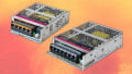
Figure 3. A selection of discrete components - including loads that must receive the full source voltage of the circuit in order to operate.
The only way for a load device to receive the properly rated voltage is to be the only load device in that circuit. If we wish to run two coils from the same control device, they must NOT be placed in series or they will only receive a portion of the supply voltage, and both will fail to run.
If we need to run multiple load devices, they must exist in unique circuits where they are the only resistance between the control devices and the P/S ground (or neutral).
Just like the control devices, the load will also drop 0 volts if ‘off’ or the full supply voltage if ‘on’. Any measurement between 0 and full supply voltage indicates a fault in the circuit. Even choosing a smaller gauge wire can introduce a slight voltage drop which leads to heat dissipation in the wire and possible failure of the load device.
One argument may be to choose a power supply with two times the rated voltage and ensure that every load is placed in series with a second identical load, thereby dropping half of that doubled voltage. Several problems with this strategy — all loads must be in series or risk damage from over-voltage, all loads must have identical resistances to the load in series (even a 24V relay from a different manufacturer may have a different resistance), and finally, if a load fails, it will also disable the other load in series, creating twice the problems.
Series Resistance Formula
Even though we do not often place resistors in series for control circuit applications, it still happens in many cases (like placing coils in series when wiring 3-phase motors). The formula is really quite simple. The total resistance is the sum of all resistors between the two points of measurement.
$$R_{total} = R_1 + R_2 + ... + R_n$$
Series Control Devices for Industry Control Circuits
The knowledge of series circuits from a textbook is completely valid for many industries. However, for these industrial control circuits, “series” often means series control devices, and our measurements will swing between 0 and the full supply voltage of the circuit. Much to our relief, the calculations and wiring are simpler, but it does emphasize the fact that circuit analysis is certainly not the same process for every person in every field of study.
Related Content