Facebook
 Google
 GitHub
 Linkedin
Fundamentals of Hydraulic Pumps: Types and Operating Principles
Hydraulic pumps take energy from a source, usually an electric motor or combustion engine, and turn it into a usable force to complete work. What kind of hydraulic pumps exist, and how do they work?
What is the Purpose of a Hydraulic Pump in a Fluid System?
Hydraulic pumps are the driving force behind all hydraulic fluid systems. They are an efficient way of transferring energy from a source to the component where the force needs to be applied. Since liquids are practically incompressible most of the input energy is transferred through the liquid with very little waste energy, making hydraulics an efficient form of energy transfer.
The purpose of a hydraulic pump is to take energy from a source, usually an electric motor or combustion engine, and turn it into a usable force to complete work. Hydraulics pumps have the capability of creating tremendous forces in order to perform heavy lifting, create clamping forces, bend objects, or myriad tasks that require a big mechanical advantage.
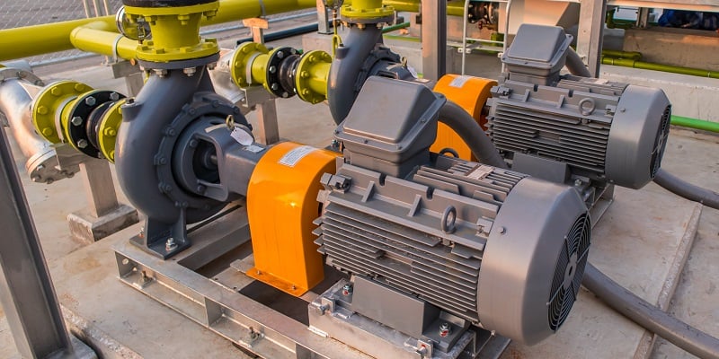
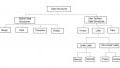
Figure 1. Large industrial water pumps with electric motor drives. Image used courtesy of Adobe Stock
The Difference Between Hydraulics and Pneumatics
Hydraulics and pneumatics function in a similar manner in that mechanical energy is transferred to a medium, oil or air, by a pump or compressor. The energy is then transferred through pressurized conduits to some type of actuator where it is once again turned back into mechanical energy.
There is a major difference between the two mediums, however: their compressibility.
Air is a gas, and therefore it is highly compressible, leading to different qualities in pneumatic systems when compared to their incompressible hydraulic counterparts. Since air is compressible, it acts like a spring and can store potential energy after the compressor has been shut off, leading to different safety concerns than hydraulics which store little potential energy if the pump is de-energized and any loads are removed from the actuator.
Essentially, a hydraulic pump moves a certain amount of fluid per stroke or revolution regardless of the amount of pressure in the system, resulting in the potential for extremely high PSI ratings. A pneumatic compressor works under a similar principle, but the compressibility of the air means that each stroke produces a variable amount of output. The higher the existing pressure in the pneumatic line, the smaller the volume of air moved per revolution or stroke. This relationship means that pneumatics can’t reach high PSI ratings without large amounts of waste energy through heat, so they normally operate at far lower pressures than hydraulic systems.
Since pneumatics are compressible, they act more like a spring and energy is less efficiently transferred due to losses from the compression of the air and heat in the system. Hydraulics have the potential to be much stronger than pneumatics and can be used to move heavier things, this comes at a price though, and hydraulics are generally much slower moving than pneumatics since air has a higher flow rate.
Types of Hydraulic Pumps
There are several main types of hydraulic pumps and they each have their benefits and drawbacks.
Vane Pumps
Vane pumps consist of a series of vanes that ride in slots cut into a rotor inside of an eccentricly shaped cam ring. The hydraulic fluid flows through the pump, just like water through a paddlewheel where the paddles (vanes) change in length as they move around the eccentric chamber. Sometimes, instead of rigid vanes with changing length, the pump uses rubber vanes which bend along the eccentric portion of the chamber, as shown.
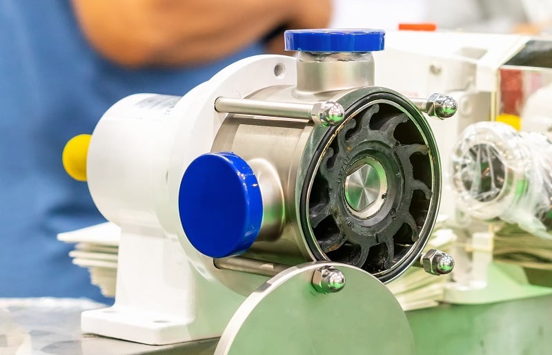
Figure 2. Rotary vane pump. Image used courtesy of Adobe Stock
Vane pumps create a constant unvarying flow rate which can be a bonus in some applications. They are also self-priming and often feature a pressure relief valve to prevent pump damage in the event that an overpressure event occurs. Vane pumps are subject to high rates of wear and may become easily damaged in scenarios where the hydraulic fluid is easily contaminated. They are often rated to produce pressure up to 3,000 PSI.
Gear Pumps
Gear pumps are commonly found in many different applications and work by pushing hydraulic fluid through two gears. Gear pumps can be categorized as either internal or external gear pumps.
External gear pumps consist of two gears spinning in opposite directions, the gears are meshed in the center of the pump stopping backflow. As the gears spin, fluid is carried around the outside of the gears from the inlet to the outlet.
Internal gear pumps consist of two gears, a larger gear that meshes with a smaller gear inside of it. The gears are offset from the center meaning only one side is meshed and the other side contains open space for the fluid to be carried across from the inlet to the outlet as the gears spin.

Figure 3. The mechanism of an internal gear pump where the shaft is centered, but the outside gear is offset during rotation.
A variation of the gear pump is the rotary lobe pump which operated using the same basic principle, but employs a set of lobed rotors instead of gears, reducing the friction and wear of the components, increasing the service life.

Figure 4. Rotary lobe pump. Image used courtesy of Adobe Stock
Gear pumps are efficient and carry a consistent amount of fluid per revolution. They are also resilient and can be used in applications where hydraulic contamination is a concern. They are commonly able to operate at pressures of 3,000-3,500 PSI.
Piston Pumps
Piston pumps are a strong, low-noise type of hydraulic pump. They are capable of producing pressures of 6,000 PSI or more, making them ideal for high pressure applications.
They consist of several pistons in a ring of cylinders that rotates around a shaft. The shaft contains a plate on an angle (called a ‘swash plate’) that determines the stroke of the pistons. As the shaft rotates and the pistons ride on the inclined plate moving in and out of their cylinder. They alternate from creating a vacuum on the inlet side by increasing the volume of the cylinder for half the cycle to then decreasing the volume of the cylinder as the piston moves in the opposite direction toward the outlet thus creating pressure.

Figure 5. Piston pump. Image used courtesy of Adobe Stock
The output of piston pumps can be changed by increasing or decreasing the angle of the inclined plate in the pump.
Peristaltic Pumps
In cases where the liquid must remain inside the pipe or tube to eliminate contamination (like medical or food & bev applications), there are a limited number of options. For smaller flow rates, lobes compress the flexible wall of the tube while rotating, squeezing the fluid through the tube and generating pressure and fluid flow.

Figure 6. Peristaltic pump with small electric motor drive.
Centrifugal Pumps
In many fluid motion systems with large volumetric output (including water delivery systems), the rotational energy is transferred to vanes inside a chamber. These vanes make up the 'impeller', forcing the fluid to the outside of the chamber, exiting through the outlet on the side. The rotational transfer of energy is similar to the operation of a centrifuge device, so these pumps are given the label of centrifugal pumps.
Due to the motion of the liquid in the impeller chamber, the flow is very rough, leading to problems of cavitation and wear on the impeller blades, reducing the lifespan of the pump. Additionally, since the motion of the impeller blades creates a suction force on the inlet in order to provide positive pressure eon the outlet, the pump must be filled with liquid in order to begin providing pressure. This process is known as 'priming' the pump. An example of a centrifugal pump is shown in Figure 1, wit hthe fluid inlet at the center of the impeller chamber, and the outlet along the left side of the chamber.
Hydraulic Pump Power Options
Hydraulic pumps can be powered in different ways and many use internal combustion engines to power them, especially in the case of heavy equipment, farm machinery, or mining equipment. Combustion based power is advantageous in scenarios where electrical power is not readily available in remote locations.
Pumps can also be powered by electric motors for stationary applications such as those in the robotics industry or other industrial processes where electrical power is readily available.
Lastly, hydraulic pumps can be powered through the use of pneumatics. This gives a unique combination that allows for pneumatic systems to increase their lifting power by transferring their energy directly into a hydraulic system. Pneumatic to hydraulic systems can give pressure ratios up to 400:1 greatly increasing the lifting power of the pneumatic system. The type of power plant used to drive the pump is highly dependent on the specific circumstances of each application.
Fluid Power in Automation
Hydraulic pumps take mechanical energy and transfer it through a hydraulic medium to perform work on different types of processes. They allow for big mechanical advantage possibilities to apply large forces where necessary.
There are many types of hydraulic pumps, including these vane, gear, piston, peristaltic, and centrifugal models, each having its own distinct advantages and disadvantages. Beyond the main categories, there are many variations to fit specific fluid motion applications.
Hydraulics are slower than pneumatics but can deliver more power without storing potential energy when the pump shuts off like in the case of a compressor, where compressed air still exists in the line.
Powering a hydraulic pump is dependent on the environment and application of the pump but they can be powered with combustion engines, electric motors, or with pneumatics.