Facebook
 Google
 GitHub
 Linkedin
Info Byte: Definition of Pressure and Flow in Fluid Systems
Pressure and flow rate are terms used in all areas of hydraulic and pneumatic systems. Learn the definition and science of these terms, and the reason they are so important within industry.
Fluid systems exist alongside electrical controls in virtually every industry. The ultimate purpose of any fluid system, gas or liquid (hydraulic), is a flexible transport of force from one location to another, in order to make motion occur.
In this article, we’ll investigate the scientific terms that define how fluids move and interact with their environment and then discuss the basic components that shape that motion inside a fluid system.
Fluid Mechanics and Terms
Definition of Pressure
The goal of the fluid circuit is to move a load, usually a cylinder pushing or pulling an object. Pressure is our ability to define the strength of the push or pull. To understand pressure, we should first look at the force, or the strength, of the fluid.
Every cylinder has a size, and this directly relates to the strength of the force. But the size of the cylinder is not the only factor affecting the force. The equation to figure out the strength of the pushing or pulling force considers two factors: the surface area of the object, and secondly is a force applied equally to every exposed atom of that surface area.
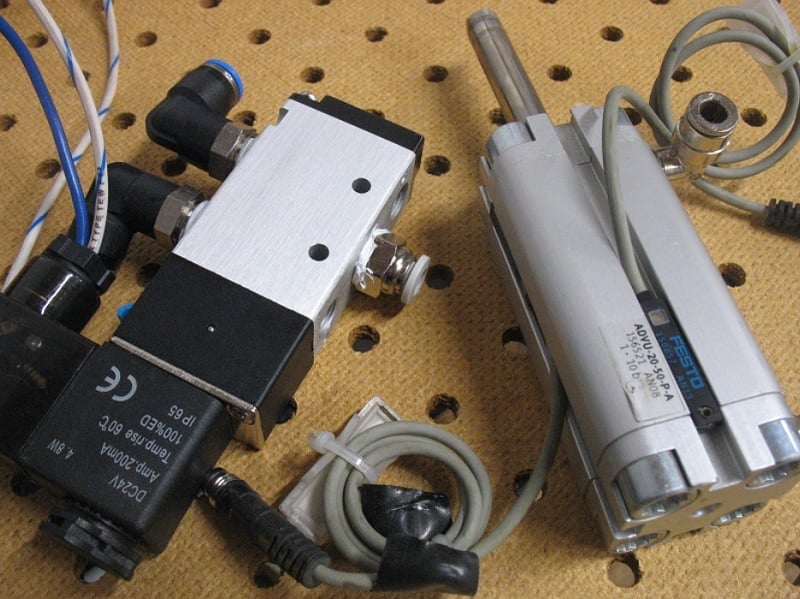
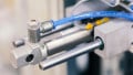
Figure 1. Pneumatic valve and cylinder
That ‘force applied equally across the surface area’ is the definition of pressure. For every tiny square inch (or square millimeter, or square meter) of space, more force is provided.
Pressure can then be defined as “a force distributed over a surface area.”
Mathematically, it looks like this:
$$Pressure = \frac{Force}{Surface~Area}$$
If we instead wish to figure out the amount of force that will be applied to an object, a slight rearranging of the equation above yields the definition of fluid force as “the product of a pressure acting on a surface area.” Increasing either factor will provide more force.
$$Force = Pressure \times Surface~Area$$
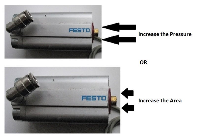
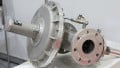
Figure 2. Two methods of increasing force - increase pressure or bore size
Definition of Flow Rate
For work to be accomplished, there must be motion (a physics pro would say work requires both a force and a distance moved). We can measure the fluid traveling through the tubes as it expands or contracts the cylinders or other loads.
The fluid does not need to be moving quickly - in fact, in many hydraulic systems, the fluid actually moves quite slowly.
Motion inherently involves a speed, like driving down the highway. The problem with a fluid is that it isn’t just a single geometric object, rather a mass of trillions of tiny molecules filling up the entire pipe or hose around it as it travels. Therefore, the speed of a fluid is not simply the distance moved every minute, but rather the volume moved per minute.
The flow rate of pneumatic systems in common English units is represented in volume and time units below:
$$Flow~Rate~(Q) = \frac{Cubic~Feet}{Minute}~or~CFM$$
Other variations of flow rate units may include gallons per minute (GPM) for liquids, as well as metric units of cubic meters per second, or liters or second.
If we wish to increase a flow rate and move the load faster, a hydraulic pump or compressor must be selected with a sufficient flow rate - a major parameter of pump selection, usually represented like “Max CFM” or “Max GPM”. Pressure must also be sufficient enough to overcome restrictions and losses in the fluid circuit, coming up next.
Fluid System Components
Pressure Source
Fluids move and flow freely through their environment, which means the power source is ‘pushing’ the liquid or gas through the pipes. In order to push a free-flowing material, a pressure must be developed, significantly enough to move the rated load.
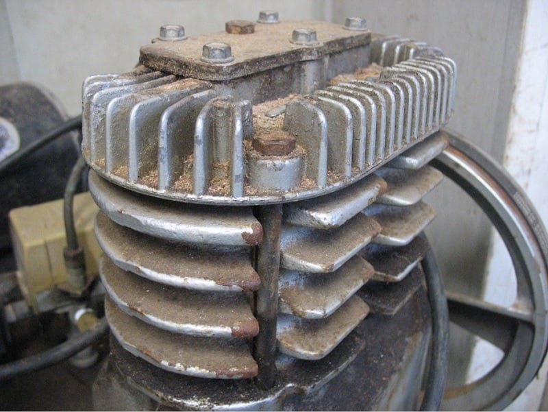
Figure 3. Small belt-driven air compressor
The power source is equivalent to a power supply in an electrical system. This supply is a ‘pump’ in a hydraulic system and a ‘compressor’ in a pneumatic system.
Caution: any air inside a hydraulic system can be damaging, likewise, fluid inside a pneumatic system can also be damaging!
The purpose of the pressure source is to develop that required pressure difference, sufficiently more pressure on one side of the load than the other, and it should move. In a hydraulic system, the lower pressure is a large fluid reservoir tank, and in a pneumatic system, the low pressure is usually the ambient air inside the facility. This is similar to a voltage difference, which must be higher on one side of the load to induce current flow.
Fluid Conductors
The hoses, pipes, and valves exist to get the fluid from the source to the load, that’s all. Again, in similarity to electrical circuits, the wires and switches exist for the same purpose.
Just like wires and switches, there will always be a bit of extra energy required simply to push the fluid through the pipes and valves. This energy consumption appears as a loss in pressure from the source to the load. The term for this is ‘pressure drop’ or ‘pressure loss’. In a perfect world, there should be zero loss, so the goal is at least to minimize such losses.
Proper sizing of pipes and valves is perhaps the single most critical aspect to minimizing losses. Internal roughness of the pipes, as well as small internal passages of valves, lead to friction, the primary culprit for pressure loss.
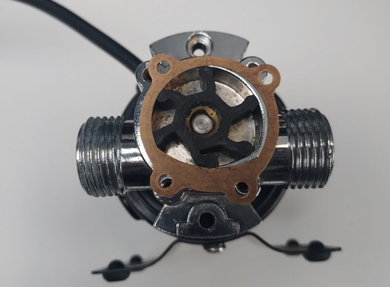
Figure 4. Small pump for water discharge system
All valves will be rated with a maximum flow rate and restrictiveness factor, usually called out as Cv, which can be referenced on a chart to determine exactly what pressure loss will be expected for any target flow rate. This loss can never be zero, no matter the size of the valve.
For the tubes and hoses, design calculators should be used, because this is no simple problem. The material and diameter of the hose, added to the length and twists in the run of the hose, will all add friction to the system.
Load Devices
Most commonly, fluid system loads are linear cylinders with a round geometry, acting much like linear actuators in an electrical system. The force required to move the object divided by the surface area of that cylinder, plus any line losses, should provide the absolute minimum required pressure from the source.
The flow rate is important in order to move the cylinder at the correct speed. The volume of fluid required to fully open the cylinder, divided by the time required to fully open the cylinder is the required flow rate. Too fast or too slow may both be a problem for the system. Remember, motion control is not about making motion happen quickly, it’s about making motion happen at the correct speed, with the correct force - flow rate and pressure are important.
Conclusion
In order for loads in a fluid system to move properly, pressure must be applied from a source, and the fluid must travel through the restrictive components at the proper flow rate in order to deliver the correct force on the load at the proper speed.
Related Content