Facebook
 Google
 GitHub
 Linkedin
Strain Gauges: Basic Operating Principles, Materials, and Properties
For being no more than a thin piece of metal, the strain gauge is a versatile measurement tool, from small switches to multi-ton machines. In this article, learn the operating principles and properties.
At first glance, a strain gauge is nothing more than a little piece of metal. It gets stretched or compressed as you push or pull it. If it is not stretched very much (a small fraction of a percent), it will return to its original position. The usual arrangement is a zig-zag pattern, having most of its pattern in one direction.

Figure 1. Strain gauges usually use a zig-zag pattern. Image used courtesy of HBM
Strain gauges are most commonly built with metal foil, but also with fine gauge wire or metal film. They need to be quite thin to have enough resistance. The majority are either 120 ohms or 350 ohms, although there are others. Sometimes they are used in arrays of two, three, or four gauges.
Below is an image of various strain gauge layouts. They include a couple of examples with more than one element on the same backing, which are called rosettes. We’ll cover them in a following article, in which we discuss applications.

Figure 2. A variety of strain gauges. Image used courtesy of HBM
“Strain”, characterized by the Greek letter Epsilon (ε), is defined as the change of length, ΔL, divided by the length, L. Strain is a unitless number. One microstrain equals one microinch per inch, micron per meter, etc. In use, most measured strains run 0.1% (1000 µin per in) or so, maybe 10,000 microstrain maximum.
“Gauge Factor” is also a unitless number. It is defined as the ratio of fractional change of the resistance, ΔR, divided by the strain, ε (ΔL/L). For metal strain gauges, the most common gauge factors are approximately 2. Some are about 3, while others may be as much as 4.
Typical Measurement Configurations
Most strain gauge configurations use two, three, or four elements. Here’s a 4-element circuit that is commonly used, called a Wheatstone bridge. Any single element may be either a strain gauge or a fixed resistor.

Figure 3. Wheatstone bridge. Image used courtesy of the author
Here’s how a Wheatstone bridge works. In our example, each resistor is 350 ohms (a typical value for a strain gauge). Assume that each resistor is configured to drop 5 volts from a 10 volt supply in the natural state.
Now, if resistor R2 increases by 0.2% (350.7 ohms) and the others do not change, the voltage of R2 (also the value of +Vout) will be 5.005V. However, -Vout would remain at 5.000 volts. The result is that the difference between +Vout and -Vout will become 5 mV (0.005) instead of zero.
Quarter, Half, and Full Wheatstone Bridges
A quarter bridge uses only one strain gauge. The others all are fixed resistors. The fixed resistor, R1, would usually have the same resistance as the strain gauge resistor, R2.
A half bridge uses two identical strain gauges, R1 and R2. If the fixed resistors (R3 and R4) are the same, the bridge will be balanced; that is, zero difference. Then, if one element is stretched (R2, resistance increased) while the other is compressed (R1, resistance decreased), there will be a difference. Using both elements doubles the sensitivity.
In some applications, only one gauge is active: the other is held firm and does not move. The usual reason is that both gauges will vary the same way when the temperature changes so that there are no temperature-related effects.
Sometimes a full bridge is used; that is, all four legs are strain gauges. Two elements are stretched, while the other two are compressed. This arrangement creates four times as much sensitivity as a single element. Of course, there are applications where not all four elements are active or able to move. Again, this minimizes temperature variations.
To be precise, if there are two strain gauge elements but only one is active, the result would be called a quarter bridge. Likewise, a four-element bridge with only two active legs would still only be called a half bridge.

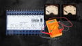
Figure 4. Close-up picture of a small strain gauge. Image used courtesy of Micro-measurements
Strain Gauge Materials
Several metal options are available for both wire and foil. The most common alloy is constantan. Others include nichrome and other alloys such as iso-elastic, dynaloy, and stabiloy. Platinum-tungsten wire also is used.
The wire or foil needs a backing material. Epoxy is often used for extended life, while cyanoacrylate is used if limited life is sufficient. Other backing materials include paper, bakelite, phenolic glass, polyimide, and others. For high temperatures, the element can be coated with ceramic cement or flame sprayed. The choice of the backing material may affect the characteristics of the strain gauge itself.
Temperature Effects on Strain Gauges
Modest temperature changes can cause significant errors. In a good resistor, the TCR (temperature coefficient of resistance) may be as low as 10 ppm/ºC. At 20 degrees C, the resistance change would be 0.02%. However, if the maximum strain range is, say, 1,000 microstrain, the span of the change would be 1,000 times as much, or 20% of the range.
This problem can be solved by using a half bridge so that both sides of the bridge vary equally. That way, even if each measurement changes a little, the difference remains the same, so the voltage differences do not change. The same would be true of a full bridge.
Another problem is strain caused by thermal expansion. The gauge expands at a different rate than the surface it is mounted on. The differences can be significant. This can be approximately compensated using alloys whose TCR can compensate for the coefficient of expansion of the mounting surface.
Semiconductor Strain Gauges
Semiconductors can be strain gauges, too. There are more options with semiconductors than metal, including P and N types. There are tradeoffs. P-type strain gauge factor is much higher, anywhere from 40 to 200. N-type gauge factor is negative; that is, the output decreases as the strain gets higher. P types are generally more popular and we’ll limit any details to P-type.
Linearity varies for semiconductor gauges, but it generally is poorer than for metals. The gauges with the lowest gauge factor (least sensitive) generally have the best linearity and temperature coefficient of resistance (TCR). We’ll not be discussing semiconductor strain gauges in any detail.
Applications of Strain Gauges
This ends our time on the basics of strain gauges. In the next article, we’ll cover some real-world considerations and finish with several examples of typical applications.